Multi-domained RBF Interpolants
This topic describes creating and editing multi-domained RBF interpolants:
- Creating a Multi-domained RBF Interpolant
- Compositing and Filtering the Values Used
- Selecting Domains
- Clipping and Transforming Values
- Setting the Trend
- Interpolation Parameters
- Output Options
- The Multi-domained RBF Interpolant in the Project Tree
- Interpolant and Sub-interpolant Display
- Sub-interpolant Statistics
A multi-domained RBF interpolant is an RBF interpolant that has a number of individual sub-interpolants bounded by the domains of a geological model.
- Changes to all sub-interpolants can be made by editing the parent interpolant.
- Sub-interpolants can be edited to account for local influences on the values used, the trend and interpolation parameters.
A multi-domained RBF interpolant is a single object that can be evaluated as a single column on points and block models.
Creating a Multi-domained RBF Interpolant
Creating a multi-domained RBF interpolant is a two-step process:
- Selecting the values to be used and the domains in which sub-interpolants will be created.
- Setting the multi-domained RBF interpolant’s properties.
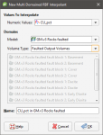
To start creating a multi-domained RBF interpolant, right-click on the Numeric Models folder and select New Multi Domained RBF Interpolant. The New Multi-domained RBF Interpolant window will be displayed:
In this window, select the basic parameters for the multi-domained RBF interpolant. You will be able to set additional properties once you click OK.
- Select the Values To Interpolate from the suitable data available in the project. You will be able to change how data is filtered at the next step, but you will not be able to change the values used.
- Select the domains used to generate sub-interpolants. These options cannot be changed once the multi-domained RBF interpolant has been created, although you will be able to select which volumes are used to generate sub-interpolants.
- Select from the geological models available in the project.
- If the selected Model has no faults defined, the Volume Type will be set to output volumes.
- If the selected Model is a faulted model, the Volume Type can be output volumes, faulted output volumes or fault blocks.
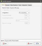
Click OK to move on to the next step. The Edit RBF Interpolant window will appear:
Compositing and Filtering the Values Used
In the Values tab, you can apply any query filters that have been defined for the data used.
When numeric values from drillhole data are used to create an interpolant, there are two approaches to compositing that data:
- Composite the drillhole data, then use the composited values to create an interpolant. If you select composited values to create an interpolant, compositing options will be disabled.
- Use uncomposited drillhole data to create an interpolant, then apply compositing settings to the interpolated values. If you are interpolating uncomposited values and do not have specific Compositing values in mind, you may wish to leave this option blank as it can be changed once the model has been created.
If you are interpolating points, compositing options will be disabled.
See Numeric Composites for more information on the effects of the Compositing length, For end lengths less than and Minimum coverage settings.
Selecting Domains
In the Domains tab, you can select the volumes in which sub-interpolants will be generated. You cannot, however, change the geological model or the types of volumes used.
Clipping and Transforming Values
In the Value Transform tab, clip data and apply a transformation, if required. See Clipping and Transforming Values for an RBF Interpolant for more information about the settings in this tab.
You will be able to change the Value Transform settings for individual sub-interpolants once the parent interpolant has been created.
Setting the Trend
In the Trend tab, you can apply a global or structural trend to the interpolant. See Changing the Trend for an RBF Interpolant for more information about these options.
You will be able to change the Trend settings for the interpolant and individual sub-interpolants once the parent interpolant has been created.
Interpolation Parameters
In the Interpolant tab, you can change interpolation parameters. See Adjusting Interpolation Parameters for more information about these options.
You will be able to change the Interpolant settings or import variogram parameters for the interpolant and individual sub-interpolants once the parent interpolant has been created.
Output Options
In the Outputs tab, you can change the parameters used to generate interpolant outputs.
The Evaluation limits apply when interpolants are evaluated against other objects in the project. When the limits are enabled, all values outside the limits will be set to the Minimum and Maximum.
Set the Default resolution for the interpolant and whether or not the resolution is adaptive. See Surface Resolution in Leapfrog Geo for more information on the effects of these settings. The resolution can be changed once the interpolant has been created, so setting a value when creating the parent interpolant is not vital. A lower value will produce more detail, but calculations will take longer.
When Exact clipping is enabled, the interpolant isosurface will be generated without “tags” that overhang the interpolant boundary. This setting is enabled by default when you create an interpolant.
To add a new isosurface, click the Add button and enter the required value. To delete an isosurface, click on it in the list, then click the Remove button. You can also change the colours used to display the isosurfaces by clicking on the colour chips.
The Volumes enclose option determines whether the interpolant volumes enclose Higher Values, Lower Values or Intervals. This option can be changed once the interpolant has been created.
Enter a Name for the new interpolant and click OK.
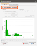
Once you have created a multi-domained RBF interpolant, you can adjust its properties as described in Changing the Settings for an RBF Interpolant. You can also change trend, clipping, transformation and interpolation settings for a sub-interpolant. To do this, double-click on a sub-interpolant. For the settings you wish to change, untick the Inherit parameters from parent box:
See also:
- Importing a Variogram Model
- Copying a Numeric Model
- Creating a Static Copy of a Numeric Model
- Exporting Numeric Model Volumes and Surfaces
The Multi-domained RBF Interpolant in the Project Tree
The new multi-domained RBF interpolant will be created and added to the Numeric Models folder. It contains objects that represent different parts of the interpolant:
- There is a link to the geological model from which domains are selected for the sub-interpolants.
- The Trend object describes the trend applied in the interpolant. See Changing the Trend for an RBF Interpolant for more information.
- The points data values object contains all the data used in generating the interpolant. See Adjusting the Values Used for more information.
- The Sub-interpolants folder contains the sub-interpolants, which can be edited to change the trend, clipping, transformation and interpolation settings.
- The Output Volumes folder contains all the volumes generated in building the interpolant.
Other objects may appear in the project tree under the interpolant as you make changes to it.
Interpolant and Sub-interpolant Display
Display the interpolant by:
- Dragging the interpolant into the scene or right-clicking on the interpolant and selecting View Output Volumes. Both actions display the parent interpolant’s output volumes.
- Right-clicking on the interpolant and selecting View Isosurfaces. This displays the isosurfaces of each sub-interpolant.
Sub-interpolant Statistics
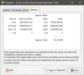
You can view the approximated mean for each output volume of a sub-interpolant by right-clicking on the sub-interpolant and selecting Properties. Click on the Statistics tab:
You can copy the information displayed in the Statistics tab to the clipboard for use in other applications.


