The 3D Scene
This topic describes how to interact with the 3D scene. It is divided into:
- Locating an Object from the Scene
- Slicing Through the Data
- Measuring in the Scene
- Working With Split Views
How to change the way objects are displayed in the scene is described in a separate topic, Visualising Data.
The best way to navigate the 3D scene in Leapfrog Geo is using the mouse. If you are running Leapfrog Geo on a laptop, it is recommended that you plug in a mouse rather than using the laptop’s touchpad for navigation. However, you can also navigate in the scene using the keyboard.
|
Action |
Mouse |
Keyboard |
|---|---|---|
|
Changing the viewing angle
|
Click and drag to rotate the scene
|
Press the arrow keys to rotate the scene For smaller steps, hold down the Shift key while pressing the arrow keys |
|
Zooming in and out of the scene
|
Use the scroll wheel Hold the right mouse button while moving the mouse |
Press the Page Up or Page Down keys For smaller steps, hold down the Shift key while pressing the Page Up or Page Down keys |
|
Panning the scene
|
Click and hold both mouse buttons, then drag Hold the scroll wheel and drag |
Hold down the Alt key while pressing the arrow keys
|
|
Centre an object in the scene |
Click the scroll wheel Click both mouse buttons together |
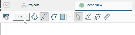
Use the Look menu above the scene window to switch to different viewing angles:
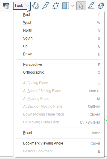
If you prefer to navigate using the keyboard, use the following keyboard shortcuts:
| Key(s) | Action |
|---|---|
| Arrow keys | Rotate the scene in 10 degree steps |
| Shift+Arrow keys | Rotate the scene in 2 degree steps |
| Home | Reset the view, showing all visible objects in scene |
| U, D, E, W, N, S | Look Up, Down, East, West, North and South |
| L | Look at the slicing plane |
| Shift+L | Look at the back of the slicing plane |
| M | Look at the moving plane |
| Shift+M | Look at the back of the moving plane |
| Ctrl+M | Look down the moving plane pitch |
| Shift+Ctrl+M | Look up the moving plane pitch |
| P | Select Perspective view |
| O | Select Orthographic view |
| Ctrl+Delete | Clear the scene |
| Ctrl+B | Bookmark the viewing angle and zoom |
| B | Display the bookmarked viewing angle and zoom |
| Ctrl+’ | Save the scene |
| Ctrl+C | Copies the scene to the clipboard. The image can then be pasted into another application, such as an image editor. |
| Ctrl+/ | Add the slicer to the scene. Press Ctrl+/ to remove the slicer from the scene. |
| Ctrl+; | Add the moving plane to the scene. Press Ctrl+; to remove the moving plane from the scene. |
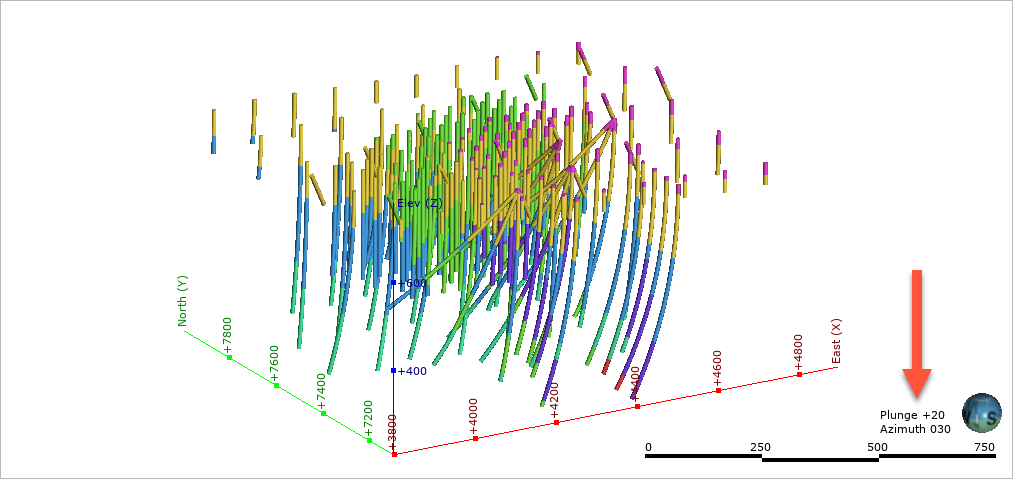
The current viewing angle and scale are displayed in the lower right-hand corner of the scene window:
You can change how the viewing angle and scale are displayed in the Overlays tab of the Settings window.
You can save the current viewing angle as a bookmark by selecting Bookmark Viewing Angle from the Look menu or by pressing Ctrl+B. Restore the bookmark by selecting Look > Restore Bookmark or by pressing B.
Only one viewing angle bookmark can be saved. The bookmark is not saved when Leapfrog Geo is shut down.
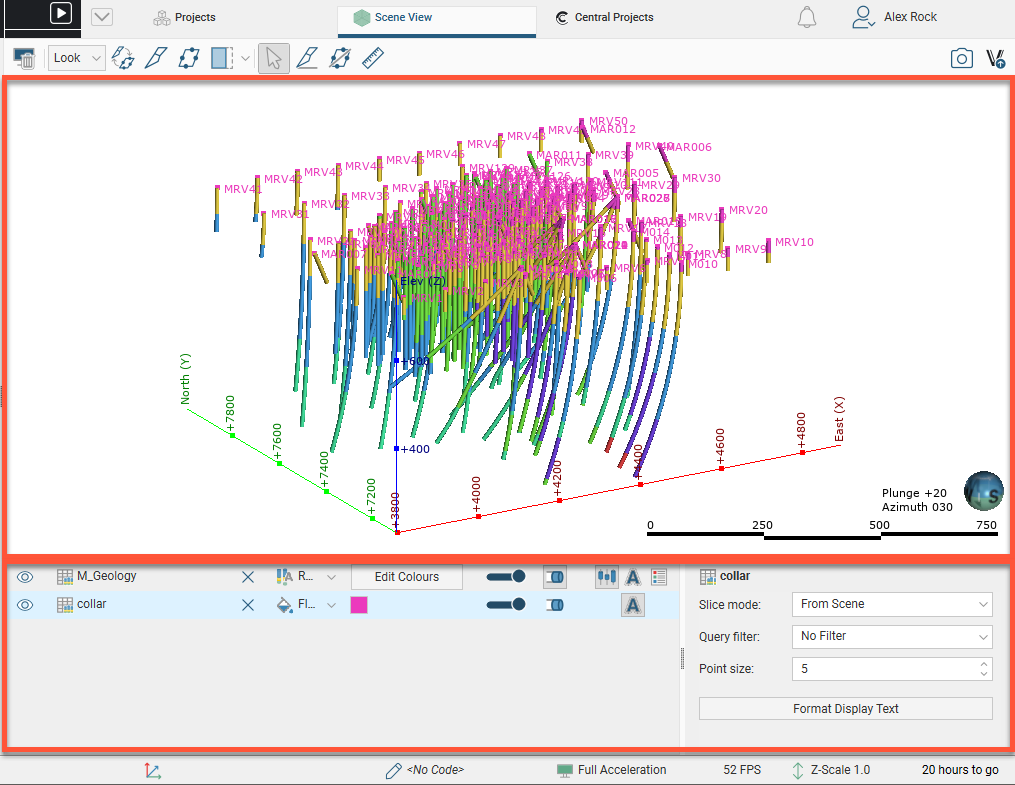
The scene window displays a 3D representation of selected data from the project tree. You can add objects from the project tree to the scene in two ways:
- Click on the object and drag it into the scene. Hold down the Shift key or the Ctrl key while clicking to select multiple items, then add them to the scene.
- Right-click on the object and tick the View Object box.
Dragging objects into the scene window may be blocked by other applications on your computer. For example, if you are sharing a screen using Skype, you will not be able to drag objects into the scene.
Once you have added objects to the scene window, you can change the appearance of those objects using the controls in the shape list and the shape properties panel.
This is described further in Visualising Data.
Changing how you view objects in the scene window does not change those objects in the project tree.
All objects in the shape list have a button (![]() ) that will remove the object from the scene. Most objects also have a visibility button (
) that will remove the object from the scene. Most objects also have a visibility button (![]() ) that can temporarily hide that object in the scene. It is often easier to make an object temporarily invisible than to remove it from the list. Some objects have an edit button (
) that can temporarily hide that object in the scene. It is often easier to make an object temporarily invisible than to remove it from the list. Some objects have an edit button (![]() ) that you can click to begin editing the object.
) that you can click to begin editing the object.
Locating an Object from the Scene
When you have a number of objects displayed in the scene, it may not be readily apparent where you can find more information about those objects. Leapfrog Geo helps you find the object in the project tree and the shape list in two ways, by Clicking in the Scene and by Clicking in the Shape List.
Clicking in the Scene
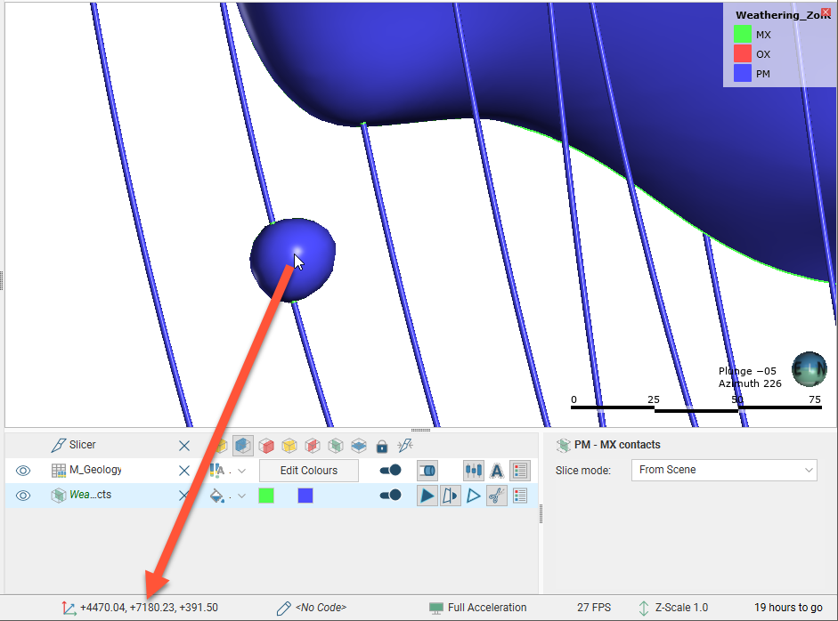
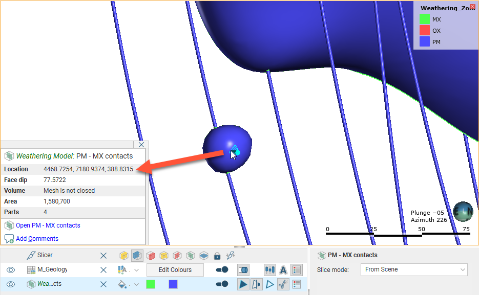
Clicking on an object in the scene displays a window that contains a summary of the data and, for many objects, a link to the corresponding data in the project tree. For example, here drillhole data is displayed in the scene and clicking on a segment displays the corresponding data:
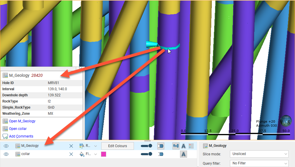
Note that clicking on an object in the scene also selects it in the shape list.
Clicking in the Shape List
When you have objects displayed in the shape list and want to locate them in the project tree, simply right-click on the object in the shape list and select Go to Project Tree:
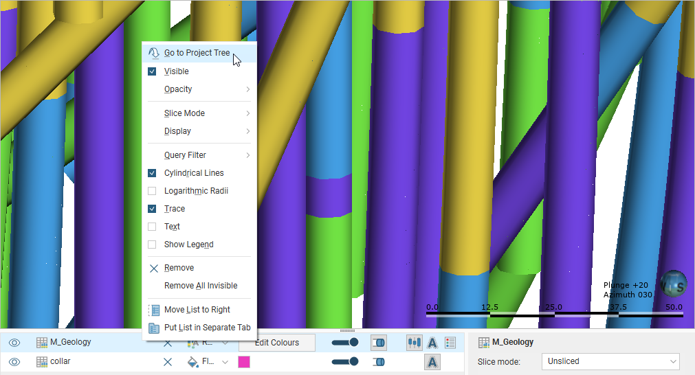
The object’s location in the project tree will be expanded and the object will be selected.
Slicing Through the Data
The slicer is a powerful tool for revealing data that is concealed behind other objects and for emphasising data. Slicing can be considered a form of dynamic sectioning.
Two buttons in the toolbar can be used to add the slicer to the scene:
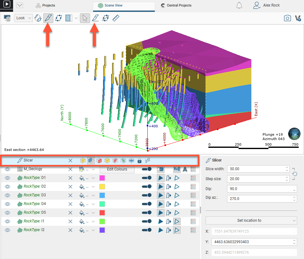
You can add the slicer to the scene by clicking the Show slicer button (![]() ). The slicer will appear in the scene and you can adjust its position using the controls in the shape list:
). The slicer will appear in the scene and you can adjust its position using the controls in the shape list:
You can also click the Draw slicer line button (![]() ), then click and drag in the scene to cut a slice through the scene.
), then click and drag in the scene to cut a slice through the scene.
The scene may appear empty because the slicer has removed all visible data. Reposition the slicer or turn it off.
Slicer Properties
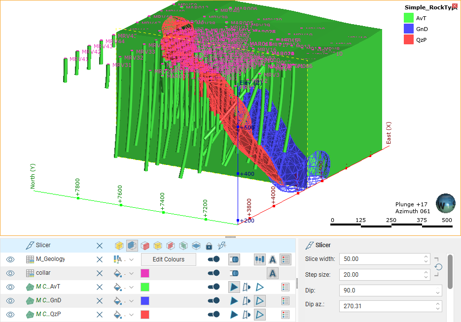
You can change the way the slice appears in the scene using the controls in the shape list, and finer controls are available in the shape properties panel:
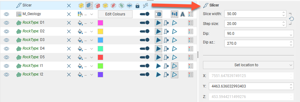
Right-click on the slicer in the shape list to view more information about each option:
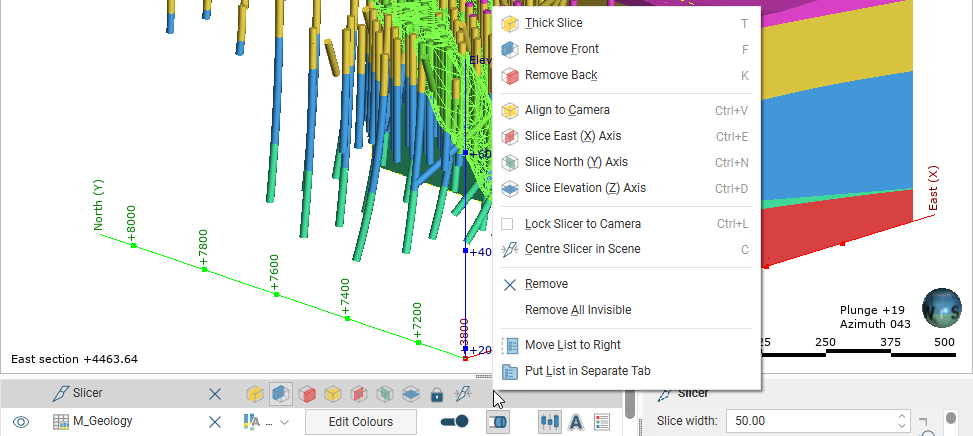
The Lock to Camera (![]() ) option locks the slice to the current view so that moving the scene changes the direction of the slice.
) option locks the slice to the current view so that moving the scene changes the direction of the slice.
These options can also be controlled from the Look menu:
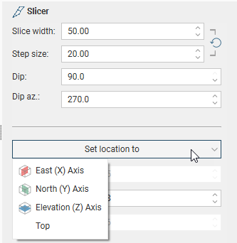
The Set location to list in the shape properties panel contains standard views, together with any sections displayed in the scene:
To move the slicing plane in a direction orthogonal to the slicing plane, hold down the Ctrl key and the right mouse button while dragging the mouse.
To change the thickness of a thick slice, hold down the Ctrl key and the middle mouse button while dragging the mouse. If you have a two-button mouse, hold both buttons.
Object Slice Mode
When you draw a slice in the scene, how objects in the scene are displayed in relation to the slicer is controlled in the properties panel for that object. For example, here the M_Geology table is selected in order to change how the drillholes are displayed in relation to the slicer:
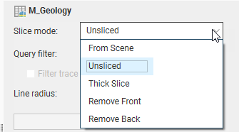
The From Scene setting is the default; the object is sliced according to the properties set for the slicer.
By changing the Slice mode for objects in the scene, you can illustrate how a model has been constructed:
Slicer Shortcuts
Use the following keyboard shortcuts to control the slicer:
| Key(s) | Action |
|---|---|
| Ctrl+/ | Add the slicer to the scene. Press Ctrl+/ to remove the slicer from the scene. |
| L | Look at the slicing plane |
| Shift+L | Look at the back of the slicing plane |
| T | Thick slice ( |
| F | Remove front ( |
| K | Remove back ( |
| Ctrl+V | Orient the slicer to the current view |
| Ctrl+E | Slice the east (X) axis ( |
| Ctrl+N | Slice the north (Y) axis ( |
| Ctrl+D | Slice the elevation (Z) axis ( |
| Ctrl+L | Lock the slicer to the camera ( |
| C | Centre the slicer in the scene ( |
| Ctrl+right mouse button | Move the slicer forward and backward in the scene |
| Ctrl+middle (or left+right) mouse button | Change the slice width |
| , (comma) | Step the slicer forward |
| . (full stop) | Step the slicer backward |
Measuring in the Scene
Leapfrog Geo has a number of tools for making quantitative measurements in the scene. These include:
- Clicking on an object in the scene. This will open a window containing more information about the object.
- Viewing an object’s properties to determine its size. Right-click on the object in the project tree and select Properties. Information on the size of the object will be displayed in the General tab.
- Using the cursor to determine an approximate location in the scene. See Determining a Location.
- Using the moving plane to measure trends. See The Moving Plane.
- Using the ruler to measure in the scene. See The Ruler.
Determining a Location
The simplest way of measuring an approximate location in the scene is to first display an object in the scene window, then position the cursor over the location. The position of the cursor is displayed at the bottom of the Leapfrog Geo window:
The position of the cursor in the scene is calculated using the depth buffer on the graphics card and so is not an exact method of measuring in the scene.
If you require an exact position, click on the object. Leapfrog Geo will compute the exact position of the point highlighted in the scene and display it in a pop-up window:
The Moving Plane
In Leapfrog Geo, the moving plane is used for measuring planar structures and defining coordinate system orientations. There are two tools in the toolbar that relate to the moving plane:
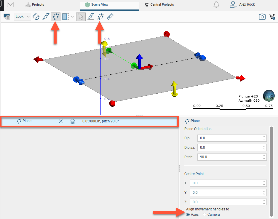
To use the moving plane, click the Show plane button (![]() ) and position the plane in the scene. The main axis of the moving plane is defined by the green line. The second axis is defined to be in the plane at right angles (orthogonal) to the main axis. Third axis is perpendicular to the plane.
) and position the plane in the scene. The main axis of the moving plane is defined by the green line. The second axis is defined to be in the plane at right angles (orthogonal) to the main axis. Third axis is perpendicular to the plane.
There are three ways to position the plane. You can:
- Use the handles in the scene window to move the plane. If you cannot see the handles, click on the moving plane.
- Use the Plane controls in the shape properties panel to change the Dip, Dip Azimuth, Pitch and Centre Point.
- Orient the scene to look parallel to the required plane position, then click on the Draw plane line button (
 ). Draw the required line in the scene.
Plane movement can be aligned to the Axes or to the Camera:
- With the Axes option, the handles move in cartesian coordinates. .
- With the Camera option, the handles move relative to the camera angle.
Drawing the plane line is usually the most convenient method of defining a planar structure.
To remove the moving plane from the scene:
- Click the Show plane button (
 ).
). - In the shape list, click the delete button (
 ) for the moving plane.
Use the following keyboard shortcuts to control the moving plane:
| Key(s) | Action |
|---|---|
| Ctrl+; | Add the moving plane to the scene. Press Ctrl+; to remove the moving plane from the scene. |
| M | Look at the moving plane |
| Shift+M | Look at the back of the moving plane |
| Ctrl+M | Look down the moving plane pitch |
| Shift+Ctrl+M | Look up the moving plane pitch |
The Ruler
You can use the ruler to measure distances in three dimensional space and between drillholes and planned drillholes.
The easiest way to use the ruler is to click on the Ruler button (![]() ) and click and drag between points in the scene to start making measurements. A ruler line will appear in the scene to indicate the measurement. Information about the distance measured will appear in the scene and in the shape properties panel:
) and click and drag between points in the scene to start making measurements. A ruler line will appear in the scene to indicate the measurement. Information about the distance measured will appear in the scene and in the shape properties panel:
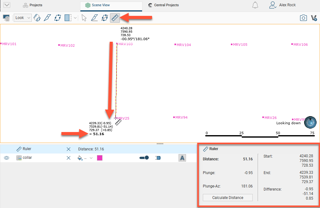
The ruler tool stays active in the scene so you can make as many measurements as required.
You can also measure the distance between drillholes or between drillholes and a point. To do this, click on the Calculate Distance button in the shape properties panel. The Distance Calculator window will appear:
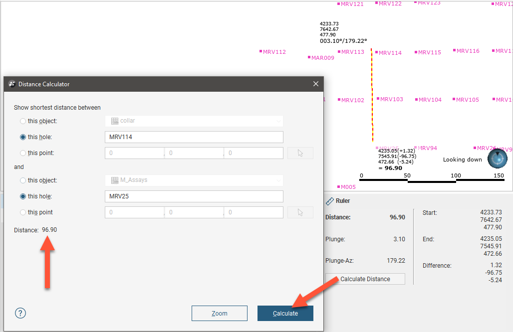
You can select both drillholes and planned drillholes. Click Calculate to calculate the distance and update the ruler in the scene. The distance value will appear in the Distance Calculator window.
You can also select a point in the scene by clicking the Select button (![]() ) in the Distance Calculator window, then clicking in the scene. The location of the point in the scene will appear in the Distance Calculator window.
) in the Distance Calculator window, then clicking in the scene. The location of the point in the scene will appear in the Distance Calculator window.
After measuring a distance, it is a good idea to change the viewing angle to confirm that the measurement has been made between the correct points in three dimensions.
There are two ways to remove the ruler from the scene:
- Click the Select button (
 ).
). - Click the delete button () for the ruler object in the shape list.
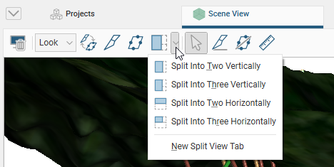
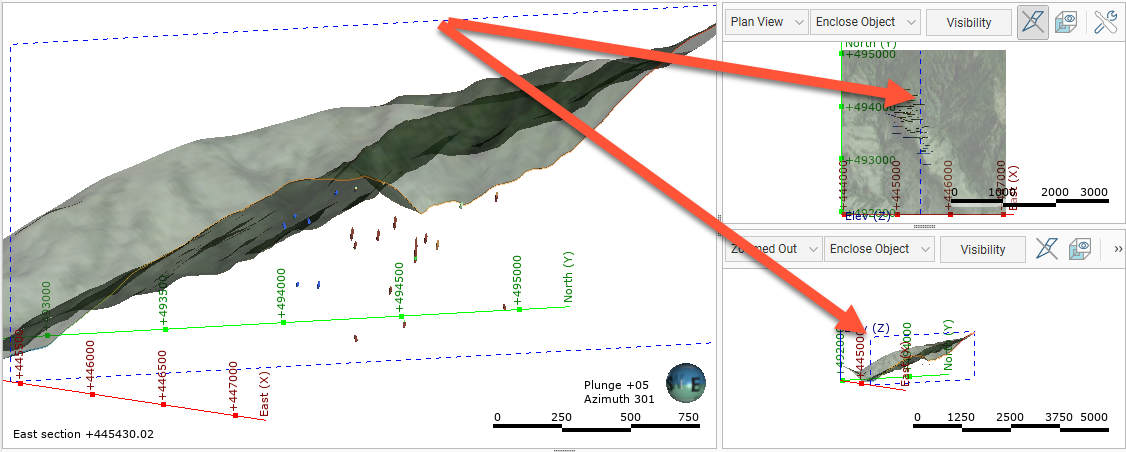
Working With Split Views
The Split View button (![]() ) in the toolbar allows you to view up to two alternative views of the objects displayed in the scene:
) in the toolbar allows you to view up to two alternative views of the objects displayed in the scene:
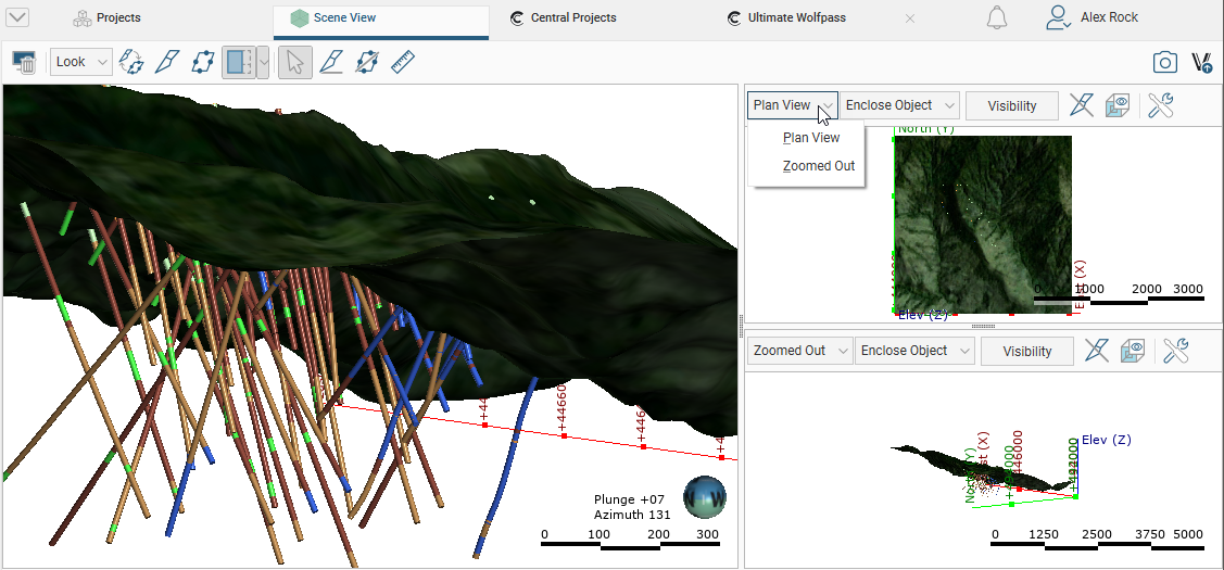
The alternative views available are a Plan View or a Zoomed Out view:
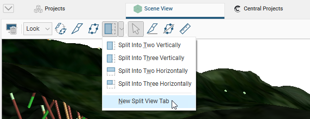
You can also open an alternative view in a new tab by choosing the New Split View Tab option:
You can resize the scene and the alternative views and Leapfrog Geo will remember the position of each view when you switch to that split view again.
To return to displaying only the scene view, click the Split View button (![]() ).
).
Each alternative view has a toolbar that gives you different options for displaying the view. Use the Enclose Object list to zoom into or out of the alternative view:
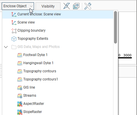
The list displayed includes all objects available in the project, plus the clipping boundary and the current scene view.
Click the Visibility button to change what objects from the scene view are visible in the alternative view:
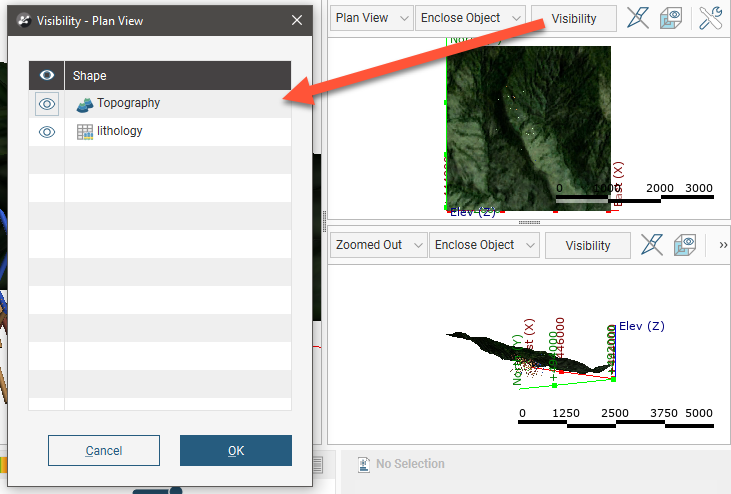
An object must be visible in the scene view’s shape list for its visibility to be controllable from the alternative view’s Edit Visibility list. What this means is that objects hidden in the scene view cannot be made visible in an alternative view.
When the slicer is in the main scene view, you can display the contents of the alternative view sliced or unsliced. Click the View Unsliced button (![]() ). The slicer, shown in blue in this image, remains displayed in the alternative views, but the view’s contents are displayed unsliced:
). The slicer, shown in blue in this image, remains displayed in the alternative views, but the view’s contents are displayed unsliced:
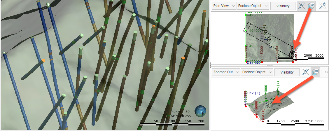
In alternative views, you can display a view window that shows what part of the alternative view is displayed in the scene view. Click the Enable View Window button (![]() ):
):
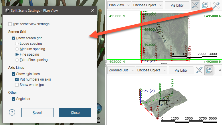
Each alternative view has a Settings button (![]() ) that lets you change what overlays are displayed for that view. The alternative view can use the scene view settings, or you can customise the display of the screen grid, axis lines and scale bar:
) that lets you change what overlays are displayed for that view. The alternative view can use the scene view settings, or you can customise the display of the screen grid, axis lines and scale bar:
Got a question? Visit the Seequent forums or Seequent support