Offset Surfaces
The offset surface tool is useful way of creating a series of deposit or erosion contact surfaces from a reference mesh. The surface can be offset from the reference mesh by points or by a fixed distance, and additional options for offsetting to points can be adjusted once the surface has been created.
Here a deposit contact surface (blue) has been created using the reference mesh (green) offset to points (red):
Important considerations when creating offset surfaces is the characteristics of the reference mesh, especially in relation to the geological model’s boundary.
- It is best to use a reference mesh that extends beyond the model’s boundary. If the reference mesh is too small, the offset surface may be distorted where the reference mesh does not occur.
- If the reference mesh changes significantly near the model’s boundary, offset surfaces may show unexpected changes. Offset surfaces are projected in the direction the reference mesh is going, and if the reference mesh changes direction just inside the boundary, that change will be reflected in the offset surface. This is normal if there is data that takes the reference mesh in a different direction, but if this is not desirable for the offset surface, consider making the geological model’s boundary smaller.
The rest of this topic describes creating and working with an offset surface. It is divided into:
- Creating an Offset Surface
- The Offset Surface in the Project Tree
- Refining an Offset Surface
- Changing Surfacing Options for an Offset Surface
- Changing Offset Limits
- Changing the Reference Mesh
- Editing the Reference Mesh
Creating an Offset Surface
To start creating an offset surface, right-click on the Surface Chronology and select New Deposit/Erosion > From Offset Surface. The New Offset Surface window will appear:
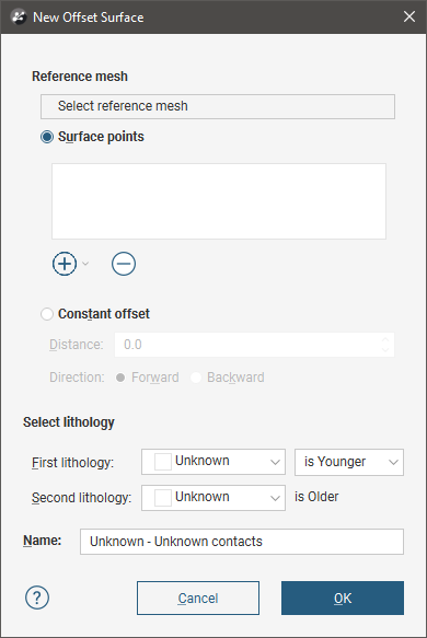
In the window that appears, you need to select a reference mesh, then either select Surface points to offset to or set a Constant offset.
Click Select reference mesh to view the meshes available in the project.
If you wish to offset from the reference mesh using a fixed distance, click Constant offset and set the Distance. For Direction, selecting Forward offsets the surface on the younger side of the reference mesh, and selecting Backward offsets on the older side.
If you wish to offset to points, click Add. You can offset to:
- Base lithology contacts or other lithology contacts in the project.
- Other data in the project. GIS data, points data and polylines can be used.
If you offset to points, you will be able to set additional options such as distance limits once the surface has been created. See Changing Offset Limits below for more information.
Select the First Lithology and Second Lithology from the lithologies defined for the model. If you have added base lithology contacts or other contacts to the surface, these will be set automatically from the data used.
Click OK to create the surface, which will appear in the project tree as part of the Surface Chronology.
The Offset Surface in the Project Tree
The name Leapfrog Geo automatically assigns to an offset surface is the lithologies assigned to each side of the surface. In the project tree, expand the surface to see how it was made:
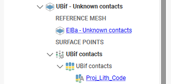
Double-click on the surface to edit it. Double-click on the contact points object (![]() ) to edit the lithology and change compositing parameters.
) to edit the lithology and change compositing parameters.
As further refinements are made to the surface, that information will also be added to the project tree. See Refining an Offset Surface below for more information.
Refining an Offset Surface
You can refine an offset surface by:
- Adding other data. Right-click on the surface to see the options available, which will depend on how the surface was created. See Adding Data to Surfaces for more information.
- Editing the surface with a polyline. Right-click on the surface in the project tree and select either Edit. See Editing Surfaces With Polylines for more information.
It is not possible to add structural data or polylines with orientation information to an offset surface. If you edit an offset surface with a polyline, your options for editing the polyline will be limited.
To edit the surface’s settings, double-click on it in the project tree. In the Lithologies tab, change the lithologies assigned to each side of the surface, if required.
You can swap the younging direction if the direction was assigned incorrectly when the surface was created. The change will be reflected in the scene. Note that changing the younging direction does not change which lithology is older or younger.
An offset surface can be created as a deposit or as an erosion. The difference between deposit and erosion contact surfaces is how they cut older lithologies, as described in Contact Surfaces. For this reason, it is possible to change between the two types using the Contact Type setting.
An offset surface cannot be adjusted by applying a trend.
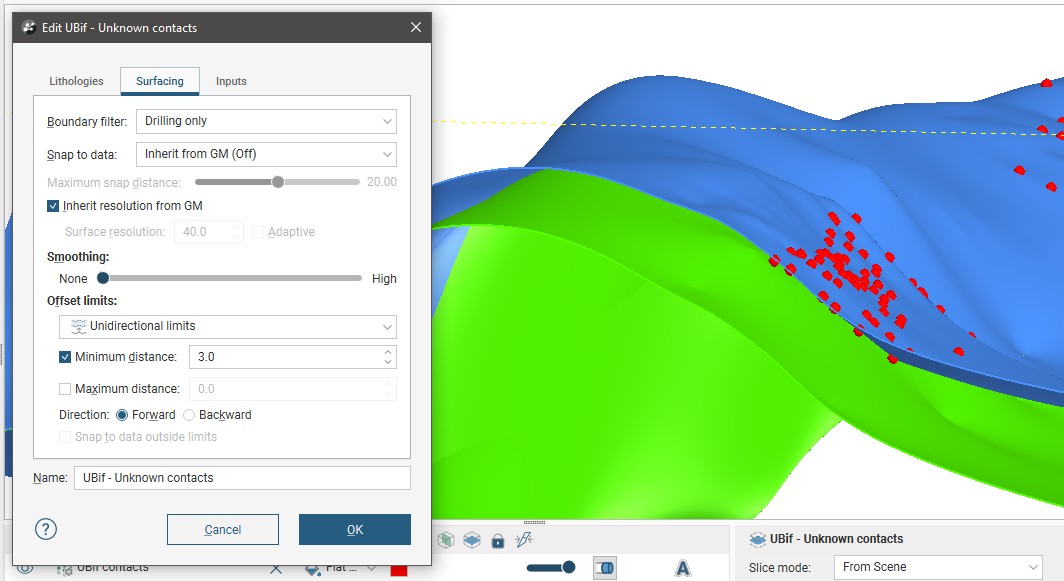
Changing Surfacing Options for an Offset Surface
Surfacing options for an offset surface can be changed by double-clicking on the surface in the project tree and then clicking on the Surfacing tab. There are additional settings related to boundary filtering and snapping to data in the Inputs tab.
Boundary Filtering
When data objects are added to a surface, there are two ways to handle the data that lies outside the surface’s boundary:
- Filter the data. The surface is only influenced by the data that falls inside the surface’s boundary.
- Leave the data unfiltered. The surface is influenced by the data both inside and outside the surface’s boundary.
The Boundary filter setting determines how data used to define the surface is filtered:
- Off. Data is not filtered.
- All data. All data is filtered.
- Drilling only. Only drillhole data and data objects derived from drillhole data are filtered.
- Custom. Only the data objects specified in the Inputs tab are filtered.
Snapping to Data
Often, surfaces should honour drillhole data and treat data objects such as polylines and GIS data as interpretations, as discussed in Honouring Surface Contacts.
There is a Snap to data setting for a geological model as a whole that is set in the Geological Model > General tab (see Editing a Geological Model). Snap to data can also be set on a surface-by-surface basis by double-clicking on the surface in the project tree and then clicking on the Surfacing tab.
For individual contact surfaces, the options are:
- Inherit from GM. The setting for the geological model as a whole is used. This is the default setting.
- Off. Surfaces do not snap to the data used to create them.
- All data. Surfaces snap to all data within the Maximum snap distance, which includes drillhole data and any data added to the surfaces.
- Drilling only. Surfaces snap to drillhole data and data objects derived from drillhole data within the Maximum snap distance but not to other data used to modify the surfaces.
- Custom. Surfaces snap to the data objects indicated in the Inputs tab for each surface.
Take care in enabling snapping and in selecting what data the surface will snap to, as the more data you include, e.g. by setting a large Maximum snap distance or selecting All data for Snap to data, the greater the possibility that errors in the data or assumptions inherent in interpretations (e.g. polylines) will cause distortions in the meshes. If you do enable snapping, it is best to snap only to drilling data. See Honouring Surface Contacts for more information on these settings.
If you need a surface to honour drillhole data but treat other data objects as interpretations, select Drilling only. To honour some data objects while treating others as interpretations, select Custom, then click on the Inputs tab to enable snapping for individual objects.
There is also a snap setting that can be used when offset limits are used. This option is discussed in Changing Offset Limits below.
Surface Resolution
The surface resolution for an offset surface can be inherited from the geological model or it can be set specifically for the surface. To change the surface resolution for an offset surface, double-click on the surface in the project tree and then click on the Surfacing tab. See Surface Resolution for a Geological Model for information about the surface resolution settings in the Surfacing tab.
Smoothing
The Smoothing parameter in the Surfacing tab can be used for all offset types other than Constant. If your reference surface is highly curved, you may see distortions in the offset surface. If this is the case, set Smoothing to a higher value.
Increasing the Smoothing parameter will generally result in faster processing when offsetting to large distances. If you are finding that processing time is excessively long for an offset surface, consider increasing Smoothing. In some situations, however, increasing Smoothing can exaggerate imperfections in the reference surface.
If you are offsetting by a small distance and processing is taking longer than expected, consider setting Smoothing to None.
Changing Offset Limits
There are four options for Offset limits in the Surfacing tab. Three relate to offsetting to points and the fourth to offsetting to a fixed distance from the reference mesh.
- The None option is the default setting used when a surface is created as an offset to points. No distance limits are used in creating the offset surface, and it simply follows the points used.
- The Unidirectional limits option allows you to set distance limits in one direction. Points outside the limits will be disregarded.
- The Bidirectional limits option allows you to set distance limits in both directions, and points outside these limits are disregarded. This setting is useful for modelling folded surfaces such as veins.
- The Constant offset option offsets the surface to a fixed distance from the reference mesh.
The Forward direction is the younger side of the reference mesh.
If the Snap to data outside limits setting is enabled, the surface will honour data, even if it is outside the distance limits. This option will be greyed out if Snap to data is off.
Changing to a Constant Offset
To use a constant offset rather than points, select the Constant offset option and set the Distance and Direction to offset the surface. Selecting Forward offsets the surface on the younger side of the reference mesh, whereas selecting Backward offsets on the older side.
If you created a surface as an offset to points and switch to using a constant offset, the points added to the surface when it was created will be disabled.
Changing to an Offset to Points
If you created an offset surface using a constant offset, you can change the surface to offset to points, but you must first add data to it. Do this by right-clicking on it in the project tree and selecting Add. Once you have added the data you wish to use, double-click on the surface and click on the Surfacing tab. Change the Offset limits option from Constant offset to one of the other three options.
Changing the Reference Mesh
To change the surface used as the reference mesh, click on the Inputs tab, then click on the reference mesh:
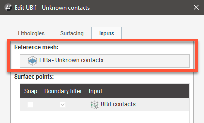
Select from the surfaces available in the project, keeping in mind the considerations discussed in Changing the Reference Mesh.
Editing the Reference Mesh
You can also edit the reference mesh as you would other surfaces. All dependent offset surfaces will be updated as you make changes to the reference mesh.
Changing the younging direction of the reference mesh affects how offset surfaces are generated.
- For a constant offset surface, the younging direction of the reference mesh determines the forward and backward direction of the offset surface and, therefore, determines the location of the offset surface. Changing the younging direction of the reference mesh results in dependent offset surfaces changing location; the updated offset surface will be the mirror image of the original relative to the reference mesh.
- For surfaces offset to points, the location is determined by the points themselves. If the reference mesh’s younging direction is changed, the offset surface’s younging direction will also be flipped. The offset surface will still honour the contact data and will still appear at the same location relative to the reference mesh.
Got a question? Visit the Seequent forums or Seequent support