
Calculate Vp
Use the Calculate Vp option to calculate the potential field at the receivers from the electrode configuration and resistivity values.
Quality Control by Electrode dialog options
|
Apparent resistivity channel |
Input resistivity channel name. This entry is mandatory. Script Parameter: IP_CALCUALTE_VP.APPRES_CHANNEL |
|
Current type |
The current can be provided either as a channel or a constant. Script Parameter: IP_CALCUALTE_VP.CURRENT_TYPE[1 – Channel specified ( default), 0 – value] |
|
Current channel or Current value |
If you selected current channel above you will be prompted to provide the channel name. Otherwise you will be prompted to supply a single current value. If you have no knowledge of the current value or if you have an indication that it few different current intensities were used, you could enter a value or 1, in which case the output potential will be the normalized potential value. Script Parameter: IP_CALCUALTE_VP.CURRENT_CHANNEL or IP_CALCUALTE_VP.CURRENT_VALUE |
|
Output Vp channel |
Channel name for the output potential at the receivers. This entry is mandatory. Script Parameter: IP_CALCUALTE_VP.OUTPUT_CHANNEL |
|
Transmitter 1 & 2 |
Transmitter 1 is required for all IP configurations. Define the channel names for the coordinates of transmitter 1. If the configuration supports a second transmitter, proceed to enter the coordinates of transmitter 2. Script Parameter: IP_ SORTBYRXTXORDER.T1X, T1Y, T1Z IP_SORTBYRXTXORDER.T2X, T2Y, T2Z |
|
Receiver 1 & 2 |
Receiver 1 is required for all IP configurations. Define the channel names for the coordinates of receiver 1. If the configuration supports a second receiver, proceed to enter the coordinates of receiver 2. Script Parameter: IP_ SORTBYRXTXORDER.R1X, R1Y, R1Z IP_ SORTBYRXTXORDER.R2X, R2Y, R2Z |
Application Notes
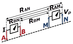
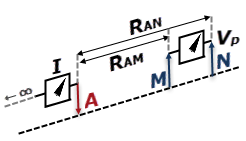
The equations for calculating the Vp are:
Dipole-Dipole Vp:

Pole-Dipole Vp:

Pole-Pole Vp:


Where ρ is the resistivity.
Got a question? Visit the Seequent forums or Seequent support
© 2023 Seequent, The Bentley Subsurface Company
Privacy | Terms of Use