
Terrain Correction (Moving Platform)
Use the Moving Platform Gravity > Terrain Corrections > Terrain Correction menu option (geogxnet.dll(Geosoft.GX.Gravity.TerrainCorrection;RunForMovingPlatform)*), to calculate the gravity terrain correction. The terrain correction results will be placed in the Output terrain correction channel (by default "Terrain" channel). The survey terrain corrections are calculated from the database, and optionally the Regional Correction Grid.
Terrain Correction dialog options
|
Survey type |
Define if the gravity survey is one of the following:
Script Parameter: GRTERAIN.SURVEYTYPE |
|
Elevation channel |
Select the elevation channel. This is the survey elevation: the ship elevation for shipborne survey or flight elevation for airborne survey. The elevation channel is optional for shipborne surveys.
Script Parameter: GRTERAIN.ELEVCH |
|
Topography (top of rock) grid |
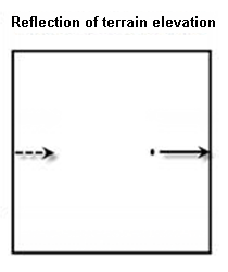
Specify the most detailed grid defining the boundary of the solid rock with air or water. If the survey area spans over multiple bodies of water, this grid defines the contact of the solid material with air over bodies of water and the contact of the solid material with air everywhere else. This grid must cover the survey area plus, ideally, the correction distance. If the Regional Correction grid is not used then this grid should also include the regional DEM data. It is generally accepted that for regional data should extend for a maximum of 300km beyond the survey area. If the grid is not large enough to cover the correction distance, the terrain is assumed to reflect on the opposite grid edges of the topography grid out to the correction distance; i.e., a traverse of the correction distance applied on an azimuth of 90 (positive X direction) would continue on a traverse to the total distance entering the topography on the west edge on the same azimuth of 90 (see the Reflection of terrain elevation diagram in the Application Notes below). Script Parameter: GRTERAIN.DEMGRD |
|
Correction distance |
Specify the correction distance. This is the distance beyond the survey area to be used for calculating the terrain effect. Script Parameter: GRTERAIN.DIST |
|
Earth density |
Specify the density of the earth in g/cm³ (the default is 2.67 g/cm³). Script Parameter: GRTERAIN.DENST |
|
If there are bodies of water in the survey area, you could specify the water level as a constant or as a grid. Specify a constant when the survey area contains a single body of water or when all the bodies of water are at the same elevation. However, if you are in a high topographic relief area speckled with lakes at different elevations, provide a grid defining the contact of material (water or solid ) with air (see the Application Notes section below). Script Parameter: GRTERAIN.WATEROPT |
|
|
Water reference elevation or DEM (contact with air) grid
|
This is a contextual entry:
|
|
Bathymetry channel |
Select the bathymetry channel (required for shipborne surveys). This is the depth of the water column (positive down). Previously, a "Water" (depth) channel was expected to be present. You now have the option to select a bathymetry channel, and if a channel named "bathymetry" exists in the database, it will be selected by default. However, to continue supporting the "Water" channel, if the bathymetry channel is not defined (there is no "bathymetry" channel in the current database), it automatically defaults to "Water" if that channel exists. Script Parameter: GRTERAIN.BATHYMETRY |
|
Water density |
Specify the water density in units of g/cm³ (the default is 1.00 g/cm³). Script Parameter: GRTERAIN.WATERDENS |
|
Output terrain correction channel |
Select the channel for the terrain correction effect. Script Parameter: GRTERAIN.TCORCH |
|
Optimize Process |
Check this option to optimize the calculations. For large DEM grids, the terrain calculation can be quite consuming. The optimization option accelerates the calculation by desampling the outer zones to a coarser averaged grid and using 4x4 points spline interpolation to determine the elevation from the grid. In the test grid dimension of 2500x2500 cells, optimization improves performance 10 times at the loss of 3% accuracy compared to not optimizing the calculations. Script Parameter: GRTERAIN.OPT |
More |
|
|
Terrain correction grid |
Specify the name of the terrain correction grid, which is calculated by the Create Regional Correction Grid tool. This grid contains the correction over the survey areas taking into account the terrain beyond the correction distance. The magnitude of the correction is normalized and will be scaled by the earth density. Script Parameter: GRTERAIN.CORGRD |
|
Local slope channel |
If local slopes have been measured at each station, select the slope channel name here. If a local slope channel is not selected, the local slope of the grid will be calculated on the fly. Script Parameter: GRTERAIN.SLOPCH |
Application Notes
Definitions:
- Topography: Rise and fall of landmass relative to sea level. Topography can extend below the surface of bodies of water.
- DEM: The Digital Elevation Model; it defines the contact of material (rock or water) with air.
The Terrain Correction option is used to calculate the full terrain corrections at each station by extracting an interpolated milligal value from the regional correction grid generated by GRREGTER GX and adding the local correction calculated from a local, more highly sampled topography grid. The correction distance is the same as the one used to calculate the regional correction grid beyond that distance.
The correction distance should be chosen carefully to avoid introducing errors to stations located near the edge of the defined topography grid. These errors may be introduced by not having a sufficiently large topography grid, such that the perimeter survey stations suffer from the terrain reflection.
Topography (top of rock) Grid
The topography grid is centred on the gravity survey area and should extend at least a correction distance beyond the edges of the survey perimeter. If the grid does not extend sufficiently beyond the survey area, such that the correction distance specified is greater than the distance between the grid outline and survey perimeter, then errors are introduced as defined above for the reflection effect.
Digital gridded terrain models are often available from government sources and can be used to simplify the application of regional terrain corrections. Also, if there are a sufficient number of known elevation points (X, Y and Elevation), a gridded terrain model can be produced by using the Geosoft RANGRID or BIGRID programs. Digital gridded terrain models are often available from government sources and can be used to simplify the application of regional terrain corrections. Also, if there are a sufficient number of known elevation points (X, Y and Elevation), a gridded terrain model can be produced by using the Geosoft RANGRID or BIGRID programs.
The topography grid should not be gridded to a cell size very much smaller than the original sampling accuracy of the DEM data. For example, if the topography is gridded from the gravity survey elevations, the grid cell size should be about one-half the nominal gravity station interval.
Terrain Correction Methods
Terrain corrections are calculated using a combination of the methods described by Nagy [1966] and Kane [1962]. The algorithm sums the effects of four sloping triangular sections, which describe a surface between the gravity station and the elevation at each diagonal corner. In the intermediate zone, the terrain effect is calculated for each point using the flat topped square prism approach of Nagy. In the far zone, (greater than 16 cells), the terrain effect is derived based on the annular ring segment approximation to a square prism as described by Kane.
For Shipborne/Airborne surveys, corrections are calculated using the flat topped square prism approach of Nagy for the near and intermediate zone, and using the rod formula [Telford et al, 1976] for the far zone.
For more processing efficiency, the far zone calculation can be optimized by de-sampling the outer zone to a coarser averaged grid (i.e. by enlarging the size of each segment to 2x2 cells for 16 to 32 cells radius, and to 4x4 cells for 33 to 64 cells radius, and so on). The calculation is carried from the Correction Distance up to the specified Outer Correction Distance.
Some special treatments are as follows. The grid is reflected on it’s edges in order to always provide corrections out to the required radius. Any dummy values in the grid will be interpolated by adjacent non-dummy values before terrain correction calculation. The system uses the grid average elevation to compensate for terrain effects in the area past the outer (regional) correction distance.
For surveys over coastal regions, the topo terrain grid would be a merge of the DTM and the bathymetry data.
The water depth in the "Water" channel should be filled with positive values if there is water under the survey station. Particularly for the shipborne survey, the water channel must be filled with positive values, otherwise the result will be a dummy grid.
*The GX tool will search in the "...\Geosoft\Desktop Applications \gx" folder. The GX.Net tools, however, are embedded in the geogxnet.dll located in the "...\Geosoft\Desktop Applications \bin" folder. If running this GX interactively, bypassing the menu, first change the folder to point to the "bin" folder, then supply the GX.Net tool in the specified format.
References
- D. Nagy, "The Gravitational attraction of a right rectangular prism", Geophysics, vol. 31, no. 2 (1966), pp. 362–371.
- M. F. Kane, "A Comprehensive system of terrain corrections using a digital computer", Geophysics, vol. 27, no. 4 (1962), pp. 455-462.
- W. M. Telford et al., Applied Geophysics, (Cambridge: Cambridge University Press, 1976), p. 59.
Got a question? Visit the Seequent forums or Seequent support
© 2023 Seequent, The Bentley Subsurface Company
Privacy | Terms of Use