
Advanced Settings
Use the Project > Settings > Advanced menu option (ADVSETTINGS GX) to change the global advanced settings for your Oasis montaj environment. The 'advanced settings' are variables that remain set for a given installation of your application. This means they remain the same for all data sets and Oasis montaj projects used on that computer. These variables include parameter settings that are used to establish the default settings in Oasis montaj, Target and other Geosoft extensions. When the application is first started, it will load the contents of the 'advanced settings' file (the geosettings.meta file in the %USERPROFILE%\Documents\Geosoft\Desktop Applications\ini directory) and set the default values across the application. In some cases, changing the advanced settings after the application has started will not change the defaults in the running program.
The Advanced Settings dialog is organized in sections. Each section has associated parameters (Attributes and Values) that can be modified to user specifications. See the Application Notes below for a listing of some of the variables and their parameters.
The General Settings option found under the Project > Settings > General menu can be used to manage some of the more common Oasis montaj global settings.
Advanced Settings dialog options
|
Application Settings |
Select any item in the Application Settings section and the associated attributes and values are displayed in the Attribute/Value table below. |
|
Attribute/Value |
The information (attributes and associated values) is displayed for each item selected under the Application Settings tree. |
Attribute Icon
The attribute icon (the white letter in a grey circle left of the Attribute column) indicates the data type, as follows:
|
|
Any positive or negative number that does not include a fraction or decimal, including zero and within the limits -32,768 to 32,767. |
|
|
An object type. It has many possibilities including a boundary polygon, another META object, and a projection object. Typically an item that can be activated by double-clicking in the particular cell. The action depends on the context and the object currently displayed. |
|
|
A number with an integer and a fractional part. The primitive types double and float are used to represent real numbers. |
|
|
A sequence of characters. Referred to as text or a text string. |
|
|
Same as Integer (above) but can only be positive or zero. |
|
|
This is a list of named values defining a range of a particular attribute type. Typically displayed as a drop down combo box for easy selection. |
 Integer
 Object
 Real Number
 String
 Unsigned Integer
 Enum
EnumAttributes and Values
The following is a small sampling of the advanced settings parameters that can be viewed and modified using the Advanced Settings dialog.
Values displayed in a grey box cannot be edited. Values displayed in a white box may be edited. The values are stored in the geosettings.meta file in the %USERPROFILE%\Documents\Geosoft\Desktop Applications\ini directory, which can be transferred to another computer if desired.
Auto Save Time
The 'Auto Save Time' setting provides a reminder dialog that pops up after a specified time interval reminding you to save any changes to the open documents:
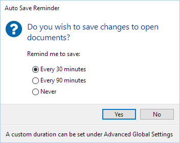
By clicking Yes in the dialog, all currently open documents (e.g., databases, grids, maps, geosurfaces, 3D views, VOXI, GMSYS projects) will be saved.
The Auto Save Reminder has three default reminder time options:
-
Every 30 minutes
-
Every 90 minutes
-
Never
To change the reminder frequency to a different custom duration, enter a new duration in number of minutes in the Auto Save Time attribute setting:
-
Select the top-level entry Application Settings: the attributes and associated values will be displayed.
-
Select the Auto Save Time attribute from the list and change its value to your desired time (in minutes).
To turn-off the auto save reminder, change the Auto Save Time value to 0 (zero).
-
Restart the application for the change to take effect.
Set Default Project Directory
Having a standard location for projects allows you to better manage where the projects are located and to facilitate an integrated workflow with a cloud storage platform.
The default location for your projects is set under your user profile Documents folder: %USERPROFILE%\Documents\Geosoft Projects. The subdirectory "Geosoft Projects" will be created if it does not exist.
To change the default location for your project directory:
-
Select the top-level entry, Application Settings: the attributes and associated values will be displayed in the Attribute/Value table below.
-
Select Default Project Directory from the list: enter a different location for your project directory and click OK.
-
New projects will be created under the specified directory.
OpenGL Settings
OpenGL (Open Graphics Library) is an industry standard cross-language, cross-platform application programming interface (API) for rendering 2D and 3D vector graphics. OpenGL drivers are usually installed together with the rest of the graphics driver and support software. NVIDIA supports OpenGL; go to
By default, Geosoft Desktop Applications will use OpenGL (version 3.3 or higher) to render high-quality 3D graphics.
Most modern video cards will support OpenGL 3.3, but in some cases (i.e., very old video cards or old/unstable graphics drivers) the 3D rendering may behave poorly.
If you suspect this:
- Your first course of action should be to update your graphics card drivers to the latest version available. From your Control Panel, open Device Manager, and under Display adapters right-click on the respective graphics card and select Update driver. Restart your computer after installing the updated video card driver.
- Next, if you have a multi-GPU system running on your system, you can "force" Oasis montaj to use a discrete high-performance GPU instead of the default integrated slower adapter like the Intel UHD graphics.
This can be needed for 3D projects that require a lot of graphical power. Most desktop computers and laptops have both an integrated Intel UHD graphics card and a dedicated NVIDIA or AMD graphics card. The integrated graphics cards are slow and consume less power while the dedicated graphics cards are a lot faster and consume significantly more power.
To specify the graphics processor Oasis montaj should use to optimize performance, you can follow the steps described in the article How to set default GPU for apps on Windows 10: in the Graphics settings dialog click Browse and select the Oasis montaj application (omcore.exe). Then, click on the Options button and select the High performance option. Once you complete and save the steps, Oasis montaj will use the specified graphics processor the next time you launch it. Expand to read more about the difference between integrated graphics and discrete graphics
 In some cases, a computer may have separate output sockets for each of the integrated and dedicated graphics cards. If you are using a laptop with external monitors (perhaps through a docking station), make sure your monitor is connected to the output port that is wired to your high-performance graphics card.
- If the issue is not resolved, or your system does not have a dedicated graphics card and the integrated graphics card is not powerful enough to handle 3D rendering, Oasis montaj’s own software rendering power may be sufficient to manage the process:
- In the Advanced Settings dialog click on the top-level entry, Application Settings, and select the OpenGL Settings section.
- In the Attribute / Value table, change the Use Software Rendering setting to True.
- This will force the 3D rendering to use “software rendering mode”, which will not rely on the graphics card.
Software rendering mode can be quite slow and using this option should be a temporary solution. A better option is to ensure that your graphics card drivers are up to date. See
Default Settings for Grids and Images
You can change the default grid display to always use the colour-shaded option, so that when grids are opened from the Project Explorer, they will appear as colour-shaded grids.
Modify the Colour-shaded Grids attribute under Image Settings in order to always show colour-shaded grids.
-
In the Application Settings tree, select the Image Settings node. The attributes and default values are displayed.
-
Set the Colour-shaded Grids attribute to True and click OK to close the Advanced Settings tool.
Any grid added to the Project Explorer will be displayed as colour-shaded when displayed in its own grid viewer window. Changes made to the shadow inclination, declination and scale inside the grid viewer are not saved between views when launched from the Project Explorer. If you wish to save changes, then save the grid view to a new map. Note that the Colour-shaded Grids attribute default value is "False" meaning that this option is off by default.
You can set up Oasis montaj so that when you select the browse button in a grid or image-related dialog or GX, the system automatically uses certain default file types and parameters (file decorations). The default file type and parameters can be changed through the Advanced Settings dialog. If you always work with specific raster or image types, you may wish to set these as the new defaults. For example, if you work extensively with ER Mapper files, you could change the 'Default XGD IN Format' parameter as follows:
-
Select the Image Settings item under the Application Settings tree.
-
In the Attribute/Value table, next to the setting called Default XGD IN Format, type in the full name of the file format you wish to use as the new default. For example, for ERS files type “ERS Mapper data (*.ers)”.
-
Restart Oasis montaj.
-
Now, when you browse for a grid file, the file type will default to the ER Mapper's ERS format.
See Also:
Got a question? Visit the Seequent forums or Seequent support
© 2023 Seequent, The Bentley Subsurface Company
Privacy | Terms of Use