
Butterworth (BTWR)
Use the Butterworth option to apply a Butterworth filter.
Butterworth Filter dialog options
|
Cutoff wavelength |
The cutoff wavelength in ground units. As shown in the illustration, this parameter is equivalent to kc-1. This wavelength is converted to wavenumber for the actual filter calculation. |
|
Filter order |
An integer representing the order (power) of the Butterworth filter. This value controls the sharpness of the cutoff.
|
|
Low pass / High pass |
Specify which range of frequencies you want to preserve:
Low pass is selected by default. |
Application Notes
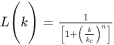
Low pass Butterworth Filter
High pass Butterworth Filter
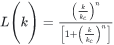
Where:
|
kc |
Inflection point of the wavenumber cutoff (cycles per ground unit). |
|
n |
Positive integer that determines the sharpness of the cutoff. |
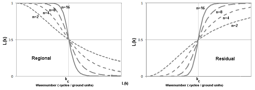
The Butterworth filter is well suited for applying high‑pass and low‑pass filtering, particularly because it allows you to control the sharpness of the filter around the wavelength cutoff. Many other low‑ and high‑pass filters introduce ringing (Gibbs' Phenomenon) due to a sharp cutoff on either side of the wavelength threshold. Ringing typically appears as wave-like artifacts radiating from the edges of strong (high-amplitude) anomalies (see below).
Original magnetic data (left), low-pass filtered magnetic data with ringing (right)
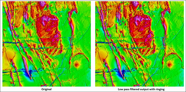
The Filter order parameter adjusts the rate of filter roll‑off around the cutoff wavenumber. Lowering the filter order reduces ringing.
If ringing is visible in the filtered output, reduce the filter order by one and re‑apply the filter.
A common—though more complex—alternative is the Cosine filter (COSN).
Got a question? Visit the Seequent forums or Seequent support
Copyright (c) 2026 Bentley Systems, Incorporated. All rights reserved.
Privacy | Terms of Use