
Directional Cosine (DCOS)
Use the Directional Cosine option to apply a directional cosine filter.
Directional Cosine Filter dialog options
|
Cut-off azimuth |
The direction of the filter, specified in degrees azimuth (clockwise from North) in the space domain. This parameter can be used to isolate or remove a predominant geological strike. |
|
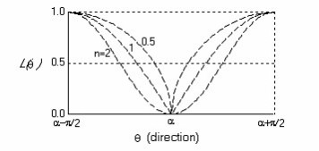
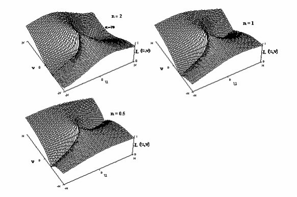
The degree of the cosine function (n). By default, a degree of 2 is used, producing a cosine‑squared response. |
|
|
|
Reject: Attenuates all wavenumbers in the specified direction. Pass: Retains only the wavenumbers in the specified direction. By default, the direction is rejected. |
 Reject
 Pass
PassApplication Notes
The directional cosine filter is used to isolate or remove signal oriented in the specified azimuth direction. The width of the rejection (or pass) notch can be adjusted by changing the degree of the cosine function so that highly directional features can be isolated more narrowly (see the filter figure below). Using a directional cosine filter instead of a straight directional pass/reject filter is recommended because it minimizes ringing artifacts associated with the discrete Fourier transform.
A common application of this filter is the decorrugation of poorly levelled magnetic data. To remove this type of signal:
-
Pass all signal along the azimuth angle perpendicular to the flight direction.
The output will contain all wavelengths in this predominant direction.
-
Apply a high-pass Butterworth filter to isolate wavelengths equal to or shorter than two line spacings.
You may need to adjust the cut-off as necessary.
-
The resulting output should contain the majority of the corrugation signal oriented normal to the flight lines.
-
Subtract this grid from the original input grid to attenuate line-to-line corrugation.
Directional Cosine Filter Illustration

|
To reject direction α |

|
To pass direction α |
Wavenumber Domain Variable Definitions
|
The following variables are used in the wavenumber domain: |
||
|
k |
Wavenumber increment, used to depict a radially symmetrical variable. |
Where: np: number of points cs: cell size |
|
μ |
X-component of the wavenumber. |
|
|
v |
Y-component of the wavenumber. |
|
|
r |
Radial component of the wavenumber. |
|
|
θ |
Angular (polar) component of the wavenumber. |
|


Got a question? Visit the Seequent forums or Seequent support
Copyright (c) 2026 Bentley Systems, Incorporated. All rights reserved.
Privacy | Terms of Use