
Directional Pass/Reject (DPAS)
Use the Directional Pass/Reject option to apply a directional pass/reject filter.
Directional Pass/Reject Filter dialog options
|
Starting cut-off azimuth |
The low cut-off angle in degrees azimuth in the space domain (geological strike). This angle is 90° offset from k0 in the frequency domain. (Starting cut‑off azimuth = k0− 90°). See the figure below for reference. |
|
Ending cut-off azimuth |
The high cut-off angle in degrees azimuth in the space domain (geological strike). This angle is 90° offset from k1 in the frequency domain. (Ending cut-off azimuth = k1− 90°). See the figure below for reference. |
|
|
Select to pass or reject the defined directional band. By default, the band is passed. |
 Pass
Pass Reject
Application Notes
Directional Pass/Reject Filter
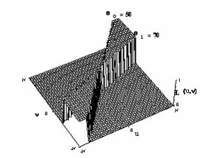
Parameters:
|
k0 |
The low cut-off angle in degrees azimuth (from North) |
|
k1 |
The high cut-off angle in degrees azimuth (from North) |
|
0/1 |
1 = pass the defined band 0 = reject the defined band (Default: 1, pass the band) |
As with a standard bandpass filter (BPAS), the directional pass filter often exhibits Gibbs’ phenomenon due to the abrupt truncation of the spectrum. For this reason, the Directional Cosine (DCOS) filter is generally recommended, as its smooth cosine‑tapered response significantly reduces ringing associated with sharp spectral cut‑offs.
Wavenumber Domain Variable Definitions
|
The following variables are used in the wavenumber domain: |
||
|
k |
Wavenumber increment, used to depict a radially symmetrical variable. |
Where: np: number of points cs: cell size |
|
μ |
X-component of the wavenumber. |
|
|
v |
Y-component of the wavenumber. |
|
|
r |
Radial component of the wavenumber. |
|
|
θ |
Angular (polar) component of the wavenumber. |
|


Got a question? Visit the Seequent forums or Seequent support
Copyright (c) 2026 Bentley Systems, Incorporated. All rights reserved.
Privacy | Terms of Use