
Sections
Leapfrog Works supports the following types of sections:
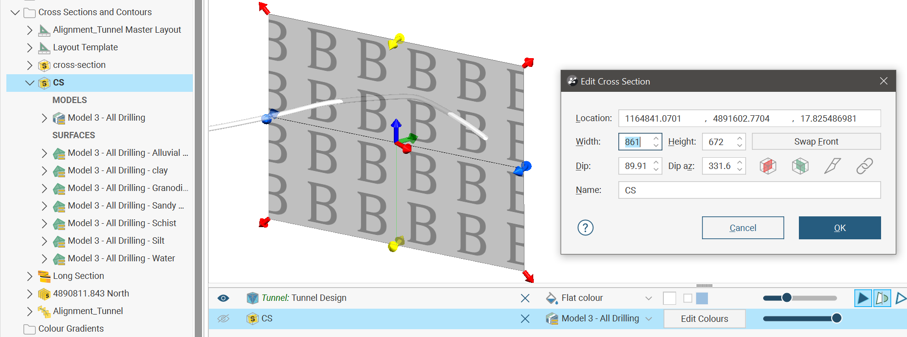
- A typical cross section is a vertical plane with an image or geologic cross section applied to it. In Leapfrog Works, this type of cross section can be created directly in the scene, from the slicer or from an imported image.
- A long section is one section or a series of sections that deviates. In Leapfrog Works, a long section can be created from a polyline drawn in the scene or from any line object in the project.
- A serial section is a series of typical cross sections taken at an offset from a single base section.
- An alignment serial section uses an imported alignment to create a series of sections along the alignment.
- A plan view is a special horizontal section providing an overview.
The rest of this topic describes:
Evaluating on Sections
Different objects in the project can be evaluated on sections, as described in Evaluations. Such objects include:
- Geological models
- Numeric models
- Distance functions
- Surfaces
- Design lines
- GIS lines
- Polylines
- Combined models
Flow models can be evaluated on cross sections but not on serial sections, alignment serial sections and long sections.
Objects evaluated on sections can be included when the section is exported.
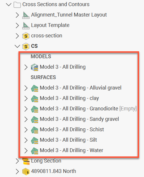
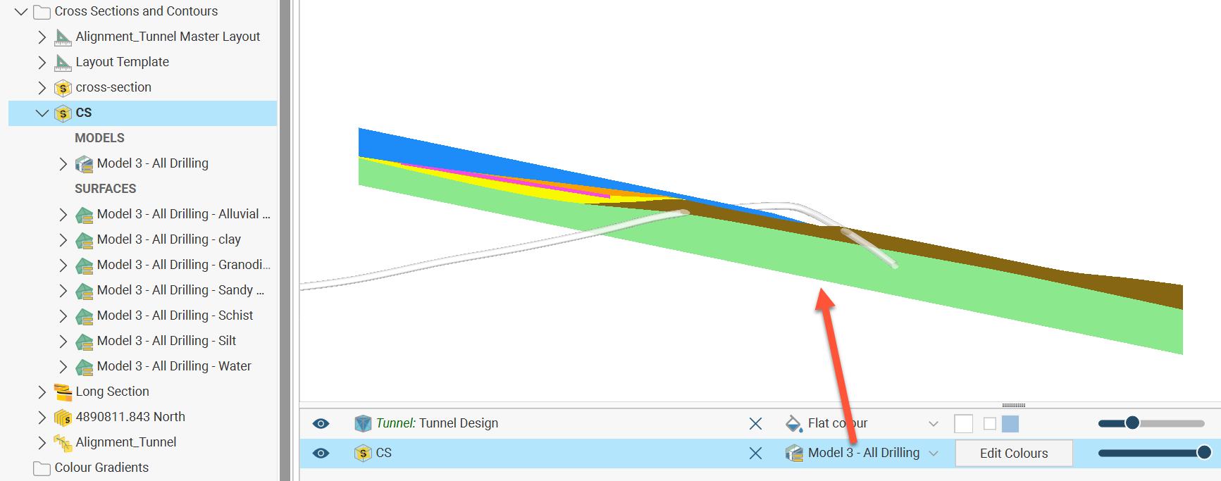
Objects evaluated onto a section will appear in the project tree under the section object, categorised into MODELS and SURFACES.
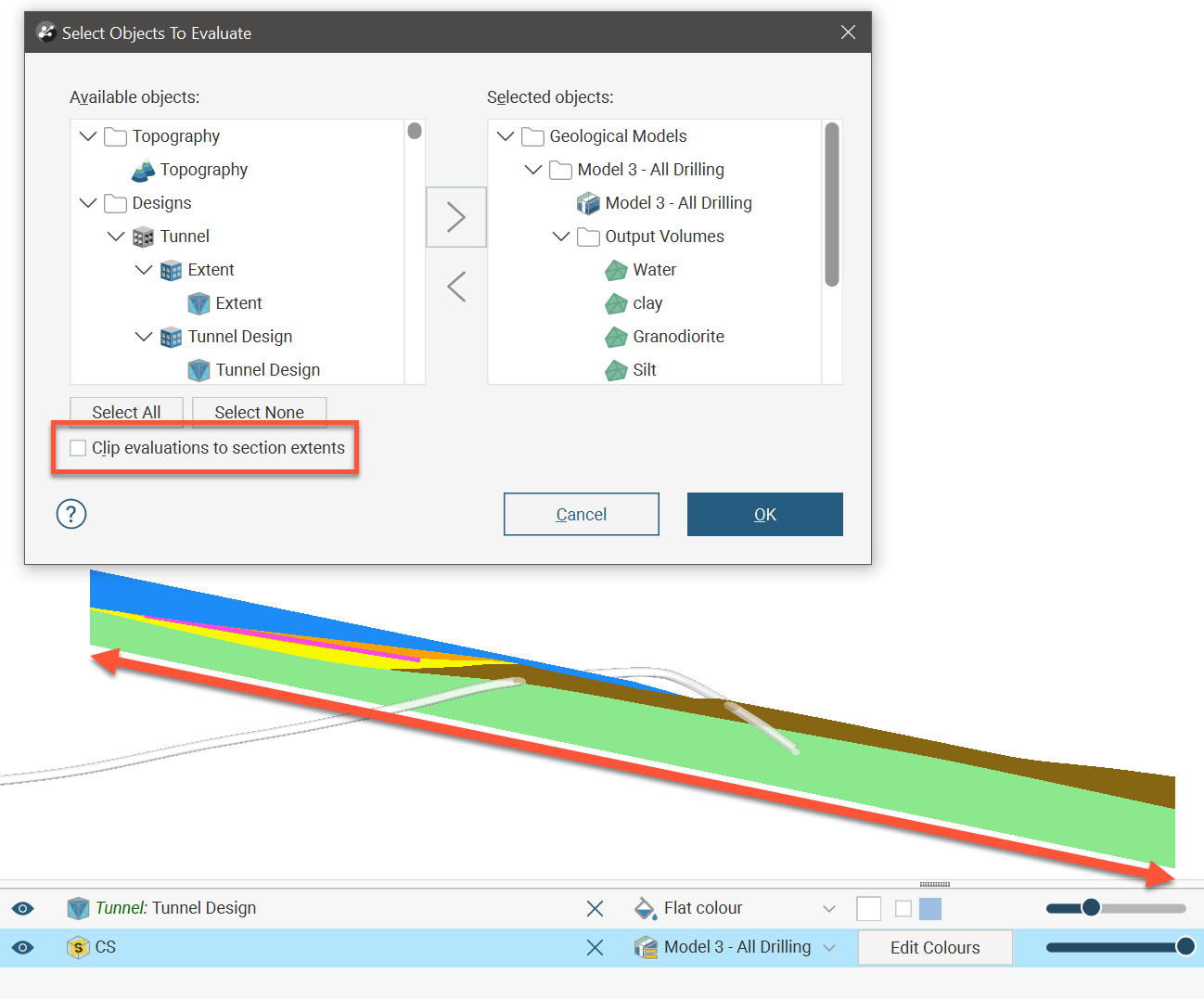
When a section layout or layout template is created and objects are added to it, they are automatically added as evaluations onto the sections the layout is applied to. However, if it is desirable to define a section without a section layout and specify what is evaluated onto the section, you can create the section, then right-click a top-level section in the project tree and select Evaluations. In the Select Objects To Evaluate window, move objects from the Available Objects list to the Selected Objects list. You can then add the section to the scene to view the evaluations on the section in the scene.
Limiting Evaluations to Section Extents
When evaluating objects on sections, you can limit the evaluation to the section extents. To do this, enable the Clip evaluations to section extents option when selecting what objects you are evaluating. This will ensure that the section appears in the scene at the same dimensions as specified when the section was defined.
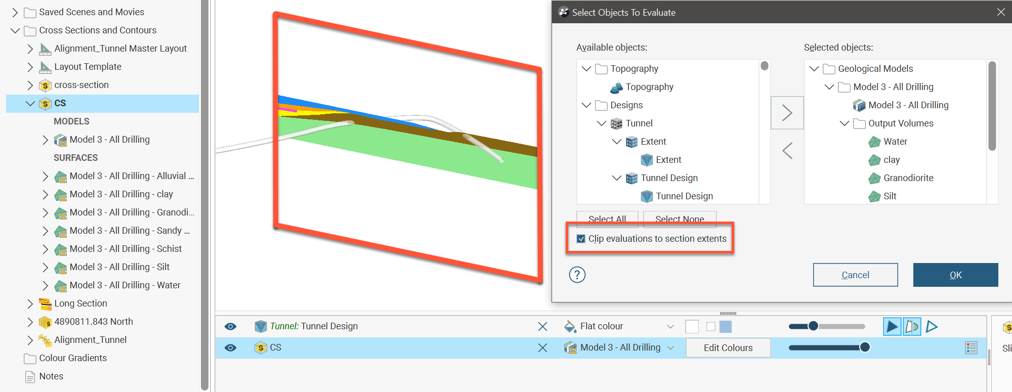
When Clip evaluations to section extents is unticked, the evaluation will continue along the plane of the section to the extent of the evaluated object.
Exporting Sections
Sections can be exported in the following formats:
- DXF Files (11/12 [AC1009]) (*.dxf)
- AutoCAD Drawing Files (2013/LT2013) (*.dwg)
- Bentley Drawing Files (v8) (*.dgn)
- Industry Foundation Classes 4.3 RC3 (*.ifc)
Another way to export a section is to create a section layout and then export it in one of the formats listed below. This option is more flexible than exporting the section as a DXF file as you have more control over the section layout. You can customise the page layout and include multiple evaluations and annotations. See the Section Layouts topic for information in using the section editor.
Exporting a section as a DXF file (*.dxf) exports a series of DXF lines created from the intersection of the evaluation volumes and the section plane. The lines generated from each volume are saved as separate layers in the file.
For serial sections, the section will be exported in a single file with a collection of DXF lines based on intersections between the selected evaluation and the section planes.
To export a section in one of these formats, right-click on the section in the project tree and select Export. In the window that appears, select the evaluations you wish to export with the section:
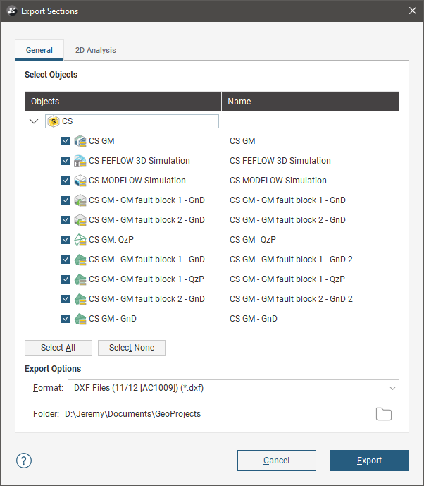
If you wish to change the name used for exporting one of the evaluations, double-click on its name, then enter the new name.
The 2D Analysis tab contains two options, Flatten to 2D and Simplify.
When you enable the Flatten to 2D option, the section will be flattened into the X-Y plane, making Z uniform across the section. You can change the origin, if required. The Flatten to 2D export option is available for:
- Regular cross sections
- Cross sections created from images
- Child sections of serial and alignment sections
- Child sections of long sections
The Simplify option is useful when the file is being exported for use in finite element slope stability packages. Enabling Simplify evens out the node spacing for model and line evaluations by setting a minimum allowable distance between nodes. Increasing the Minimum spacing setting reduces the number of nodes included but can result in loss of detail.
Note that the 2D Analysis options are not available when exporting the section in IFC format. See Exporting Section Evaluations to IFC for information about exporting sections in IFC format.
Got a question? Visit the Seequent forums or Seequent support
© 2023 Seequent, The Bentley Subsurface Company
Privacy | Terms of Use