
FEFLOW Models
These features are only available as part of the Hydrogeology extension. See Flow Models for more information.
In Leapfrog Works, creating a 3D FEFLOW model requires a geological model that will be used to assign lithologies to the FEFLOW model’s blocks.
Steps for creating a 3D FEFLOW model that can be exported and run outside Leapfrog Works are:
1. Create a geological model.
2. Create a 3D model.
3. Evaluate the new 3D model against a geological model.
4. Edit the material types.
5. Export the 3D FEFLOW model.
Once the model has been processed outside of Leapfrog Works, a results file can be saved that can be imported into Leapfrog Works and visualised in the scene.
The rest of this topic describes working with FEFLOW models in Leapfrog Works. It is divided into:
- Importing a FEFLOW Model
- Creating a 3D FEFLOW Model
- Adding Features to the Grid
- Creating a 3D FEFLOW Model From a 2D Grid
- FEFLOW Evaluations
- Assigning an Evaluation for Export
- Displaying a FEFLOW Model
- Editing FEFLOW Material Types
- Exporting FEFLOW Models
Importing a FEFLOW Model
Leapfrog Works imports:
- FEFLOW problem files (*.fem) in ASCII format. These can be 2D or 3D FEFLOW grids.
- FEFLOW results files (*.dac). Importing these files results in a new 3D model with a grid, nodes and simulation outputs.
To import a FEFLOW grid or results file, right-click on the Flow Models folder and select one of the FEFLOW > Import options. Leapfrog Works will ask you to specify the file location. Click Open to import the file.
The new FEFLOW grid will appear in the project tree under the Flow Models folder.
To associate lithologies with a 3D model, see Editing FEFLOW Material Types.
Creating a 3D FEFLOW Model
A 3D FEFLOW model can be created in Leapfrog Works with layering defined by a geological model. You can import a 2D FEFLOW grid and use it as the basis for the 3D model, or, if you do not have an existing 2D grid on which to base the 3D model, Leapfrog Works will create one for you.
To create a new FEFLOW model without using an existing 2D grid, right-click on the Flow Models folder and select FEFLOW > New Model:
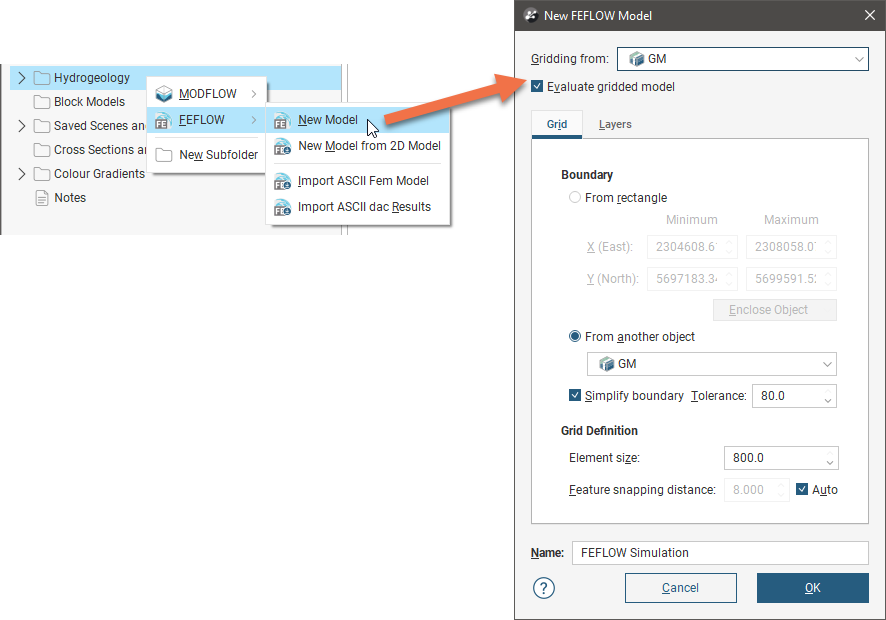
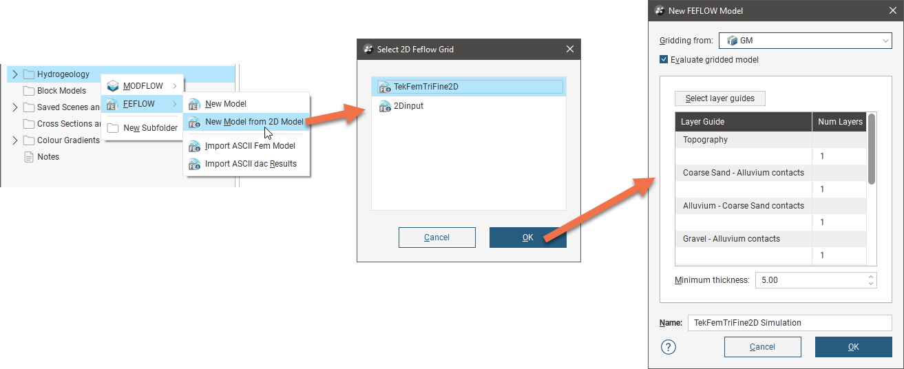
The New FEFLOW Model window will appear. In this example, a geological model has been added to the scene to aid in defining the FEFLOW model:
The Gridding from setting determines the geological model used for layer guides. Ticking the Evaluate gridded model box will evaluate the new 3D model against the selected geological model and set it as the evaluation for export. See FEFLOW Evaluations below for more information. If you do not wish to evaluate the geological model on the grid, untick the box. You will still be able to use the layers in the geological model to control the grid layers.
Once the model has been created, you can change most of its settings, but you will not be able to change the Gridding from model.
Click on the Layers tab to see the layers that will be used in the new 3D model. By default, the layers from the Gridding from model are selected as layer guides, but you can change this by clicking the Select layer guides button and changing which layers are used:
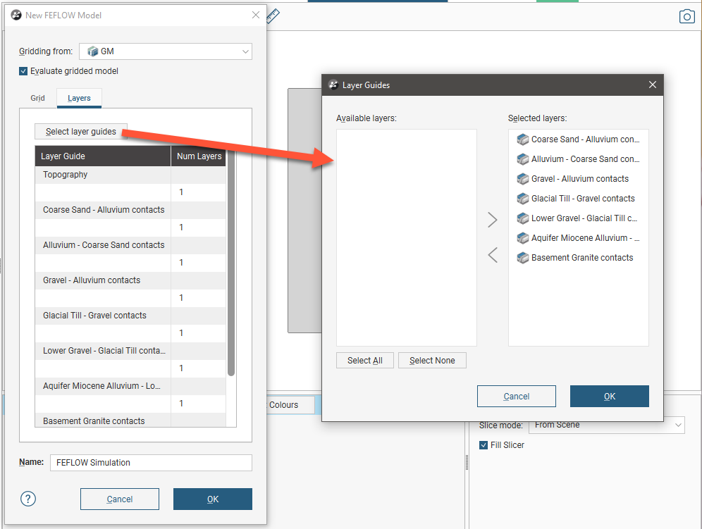
If the grid is required to follow a geological model lithology contact surface, move the layer into the Selected list and it will be honoured in the gridding process.
Once you have determined which layers you will use as layer guides, you can change how many layers there will be in the 3D model. To do this, click on a layer in the Layers tab and edit the Num Layers value:
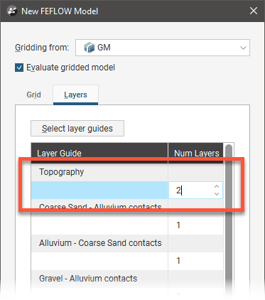
The minimum thickness of each layer is determined by the Minimum thickness setting in the Grid tab. If there is a conflict between the Minimum thickness setting and the number of layers defined in the Layers tab, Leapfrog Works will display an error message when you click the OK button to create the model.
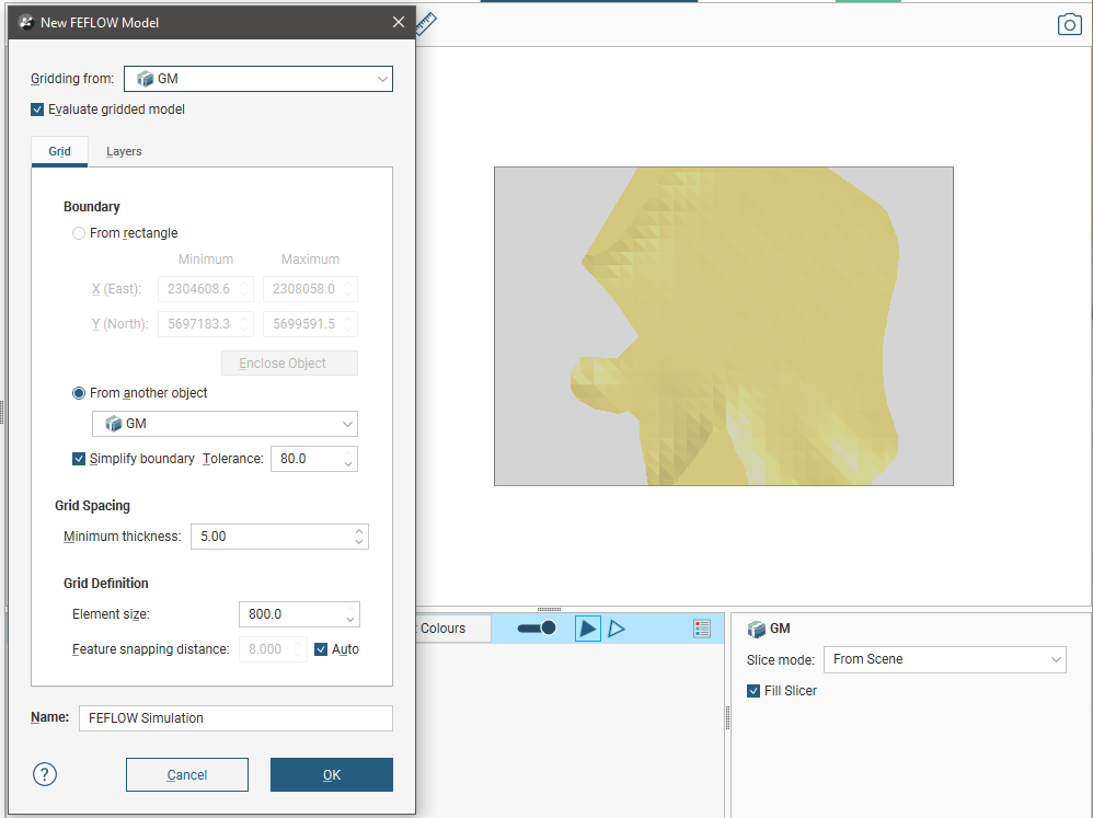
In the Grid tab, the model’s boundary can be defined as a rectangle or from another object in the project. In the example above, the geological model GM is used to define the FEFLOW model’s boundary. When the boundary is set to From rectangle, controls will appear in the scene that will help in setting the boundary:
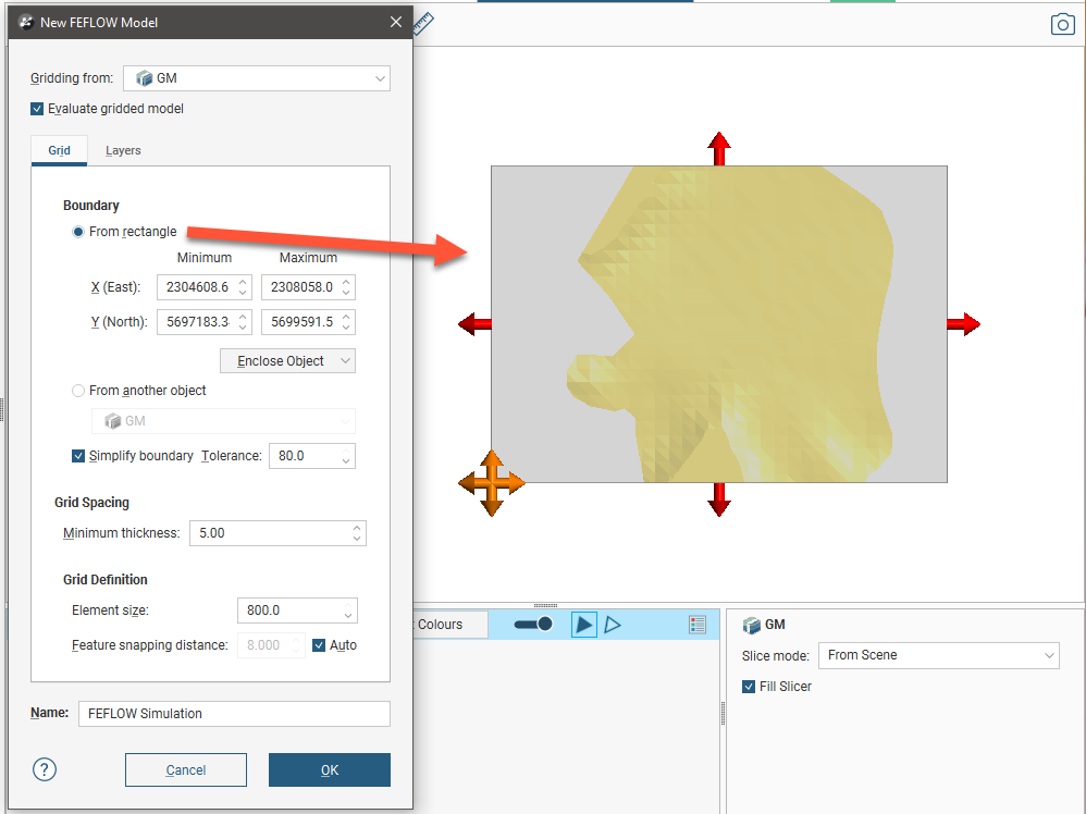
The boundaries of the Gridding from model must be larger than the boundary of the new FEFLOW model.
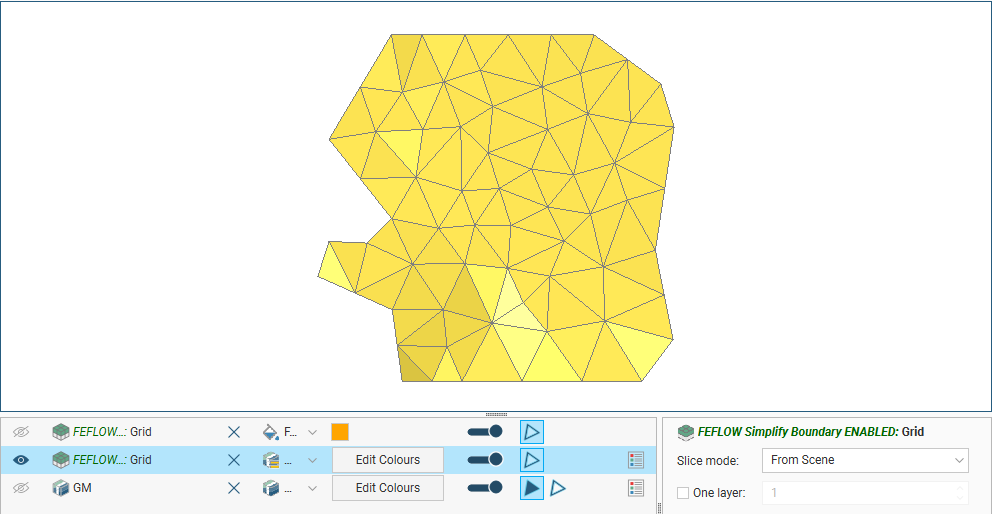
When the boundary is set from another object in the project, the Simplify boundary option can be used to reduce the number of points along the boundary. A lower Tolerance value increases the number of points along the boundary. The two settings together let you define a basic boundary with elements that are roughly uniform in size, set by the value of Element size. Here, a grid has been created from a geological model with the Simplify boundary option enabled:
Disabling the Simplify boundary option results in more detail around the edges of the grid:
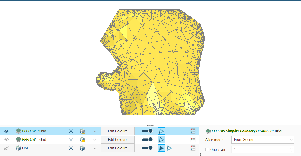
The Element size setting determines the basic size of the triangles that make up the grid, although the size will vary according to features applied to the grid and the Feature snapping distance. The size will also vary if the Simplify boundary option is unticked, in which case the Element size setting is the maximum size of the triangles.
The Feature snapping distance is automatically set to 1 percent of the Element size. To use a smaller snapping distance, untick the Auto box and set the value required.
The effects of the Feature snapping distance do not become apparent until features have been added to the grid, after it has been created, which is described in Adding Features to the Grid below.
Click OK to generate the new FEFLOW model, which will appear in the project tree under the Flow Models folder.
In the project tree, the FEFLOW model is organised into a 3D grid object (![]() ) that contains a 2D grid (
) that contains a 2D grid (![]() ):
):
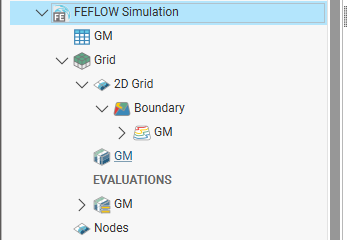
To edit model settings such as the boundary, layer guides, Minimum thickness, Element size and the Feature snapping distance, double-click on the 3D grid object (![]() ). The geological model used for gridding cannot be changed.
). The geological model used for gridding cannot be changed.
Adding features to the grid involves working with the 2D grid, which is described in Adding Features to the Grid below.
Adding Features to the Grid
You can refine the resolution of the FEFLOW model by adding features to it around objects about which you have more information, such as drilling data.
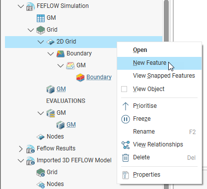
To add features to the FEFLOW model, expand it in the project tree, then right-click on the 2D grid object (![]() ) and select New Feature.
) and select New Feature.
In the window that appears, you can add points, lines and polygons to the model. Click the Select button to view the objects in the project that can be added to the model. If an object has query filters defined, you can filter the data, if required.
Select the object you wish to use, then click OK to return to the New FEFLOW Feature window.
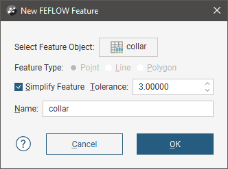
For many objects, the Feature Type setting will be automatically determined, but for polylines, you can select the Feature Type.
Ticking the Simplify Feature option will reduce the number of points used, with a lower Tolerance value increasing the number of points along the boundary.
Once you have added a feature to the grid, you can edit the Simplify Feature/Tolerance settings, but you cannot change the object used or switch to a different query filter.
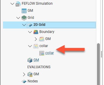
Click OK to add the feature, which will appear in the project tree under the 2D grid object:
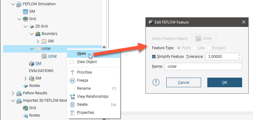
You can edit the feature by double-clicking on it or by right-clicking on it and selecting Open. In the Edit FEFLOW Feature window, you can enable or disable the Simplify Feature setting and change the Tolerance.
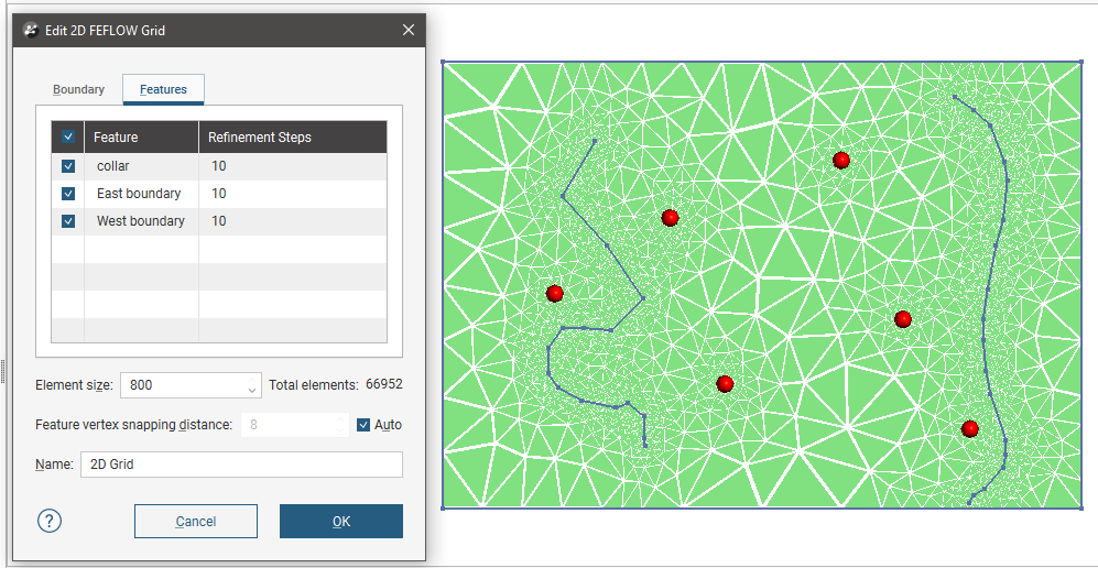
To view all features that have been applied to a FEFLOW model, double-click on the 2D grid object (![]() ). This opens the Edit 2D FEFLOW Grid window with the Features tab open, showing all features that have been added to the grid:
). This opens the Edit 2D FEFLOW Grid window with the Features tab open, showing all features that have been added to the grid:
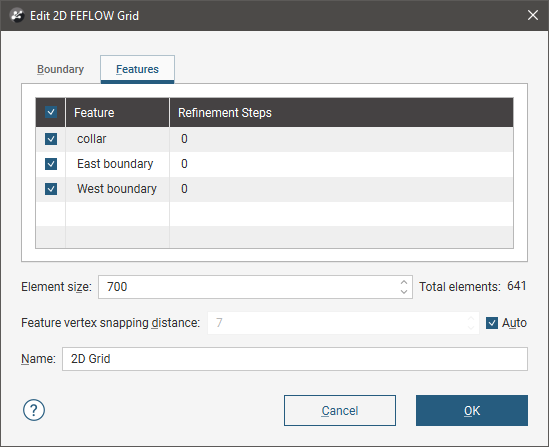
You can set Refinement Steps on a feature-by-feature basis. More steps will produce more detail near the feature.
If you want to modify a feature without having to reprocess the grid, untick it in the Features tab. If you want to delete a feature, right-click on it in the project tree and select Delete.
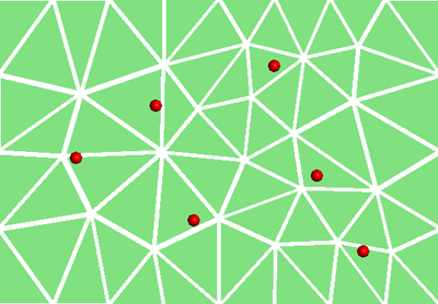
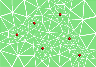
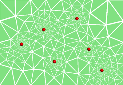
The images below show a grid displayed with collar points (in red) to demonstrate the effects of no features and collars applied with different refinement steps:
|
|
|
| No features | Collars with 2 refinement steps | Collars with 10 refinement steps |
To view all features added to a grid, right-click on the grid and select View Snapped Features. A Snapped Features object will appear in the shape list that represents all objects used to add features to the grid:
Here, four snapped objects appear in the scene: the three features listed in the Features tab and the grid’s boundary.
Creating a 3D FEFLOW Model From a 2D Grid
To create a new FEFLOW model from an imported 2D grid, right-click on the Flow Models folder and select FEFLOW > New Model from 2D Model:
The process is similar to that for Creating a 3D FEFLOW Model described above, except that you do not need to set the parameters in the Grid tab.
Once the model is created, you can evaluate models, set material types, set an evaluation for export and export the model to FEFLOW, just as you would with a model from a 2D grid created in Leapfrog Works. You cannot, however, add features to the grid.
FEFLOW Evaluations
In order to set material types for a 3D FEFLOW model and export the model, a geological model must be evaluated on the model.
- For 3D FEFLOW models created in Leapfrog Works, the geological model used in defining its layers is automatically evaluated, unless the Evaluate gridded model option is disabled.
- For 3D FEFLOW models imported into Leapfrog Works and models created in Leapfrog Works without an evaluation, a geological model must be evaluated on the model before material types can be set.
To evaluate models on a FEFLOW model, right-click on the model in the project tree and select Evaluations. You can evaluate more than one model on a FEFLOW model, but only one evaluation can be used as the evaluation for export. Interpolants and distance functions can be evaluated on the model but they cannot be exported and are simply used for displaying the grid in Leapfrog Works.
Assigning an Evaluation for Export
If only one geological model has been evaluated on a FEFLOW model, it will automatically be used as the model for export. If you have evaluated more than one geological model, you can choose which one to export by right-clicking on the FEFLOW model in the project tree and selecting Set Evaluation for Export
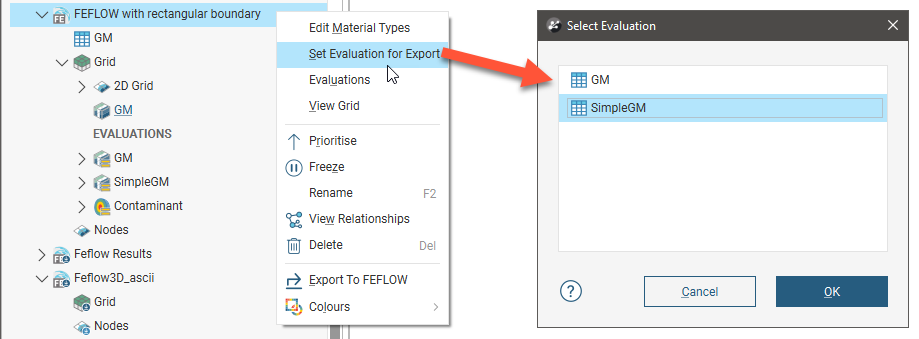
Select the model you wish to use, then click OK.
Displaying a FEFLOW Model
If you do not have the Hydrogeology extension, FEFLOW models will appear in the project tree as Restricted. You can display them in the scene, but you cannot modify them.
Dragging a 3D FEFLOW model into the scene displays its grid object, which represents the finite elements. Here, a 3D model created in Leapfrog Works(![]() ) has been added to the scene:
) has been added to the scene:
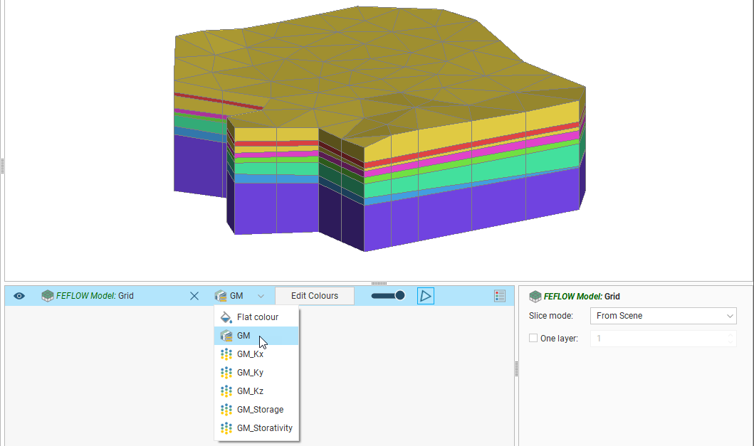
For 3D models imported into Leapfrog Works, you can display the model using other information available for the grid, such as conductivity data. This is available from the view list.
Grids for 3D models are displayed as blocks. You can also display a legend for the grid when a geological model evaluation is displayed.
When Show edges(![]() ) is enabled, the edges of the blocks will be displayed.
) is enabled, the edges of the blocks will be displayed.
To display a single layer, tick the One layer box in the shape properties panel, then select the layer to display.
You can display the nodes by adding the nodes (![]() ) object to the scene. When a model with results is displayed, the simulation outputs can be displayed when the nodes are viewed in the scene. Here, the nodes for an imported results file have been added to the scene. The heads are displayed for a single layer:
) object to the scene. When a model with results is displayed, the simulation outputs can be displayed when the nodes are viewed in the scene. Here, the nodes for an imported results file have been added to the scene. The heads are displayed for a single layer:
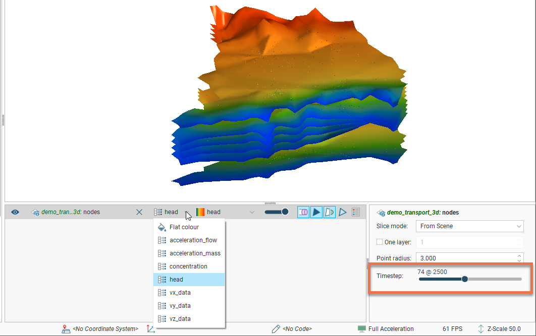
When the results are time-dependent, a timestep slider will be available from the shape properties panel. Click and drag the slider or click along the timeline to view the different timesteps available.
When a FEFLOW model is displayed in the scene, you can view information about the individual blocks in the model by clicking on a block. The window that appears shows information about the selected block, including its centroid and the lithology assigned to the block from all evaluated geological models and interpolants:
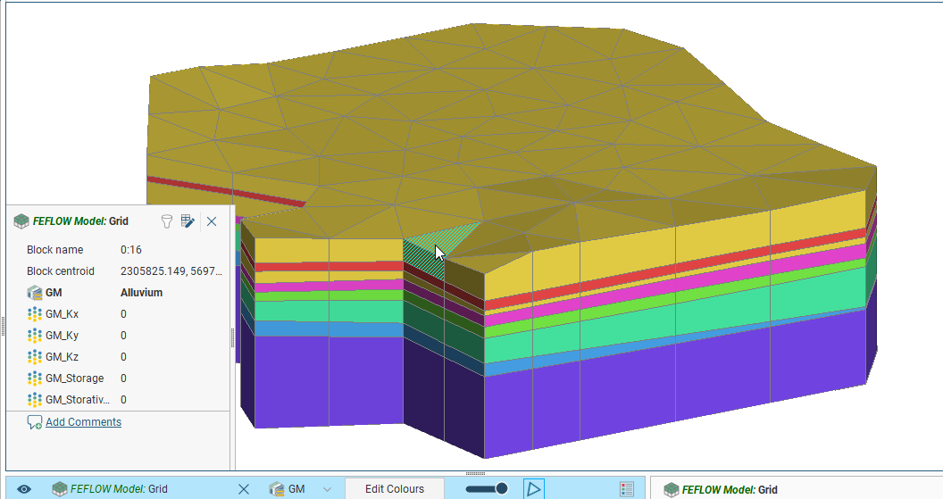
Information from all geological models and interpolants the grid has been evaluated against will be displayed:
Editing FEFLOW Material Types
To edit a FEFLOW model material types table, you will first need to evaluate a geological model against the model, which is described in FEFLOW Evaluations above.
Once a geological model has been evaluated, edit the material types table by right-clicking on the model in the project tree and selecting Edit Material Types. The Edit Material Types window will appear. If more than one object has been evaluated on the grid, you can edit material types separately for each evaluation. Select the required evaluation from the Evaluation list:
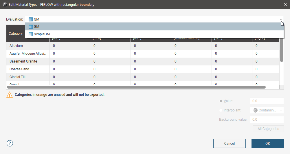
However, the only material types information that will be exported is that set for the evaluation to be exported.
Note that whether or not you set values for the initial concentration column will affect what format will be used when the FEFLOW model is exported. See Exporting FEFLOW Models below for more information.
You can enter the values for material types manually or you can use the values from an interpolant.
To enter values manually, click on a cell, then enter the value in the Value field:
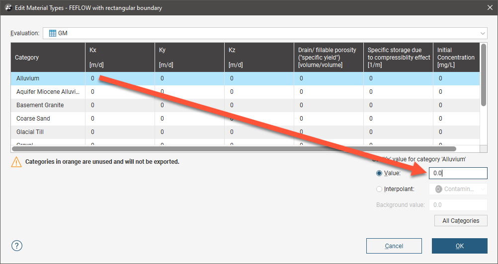
Press the Enter key to move down the columns.
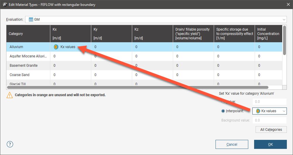
To use the values from an interpolant, click the Interpolant button, then select an interpolant from the list. The interpolant that will be used for the selected value will be displayed in the field:
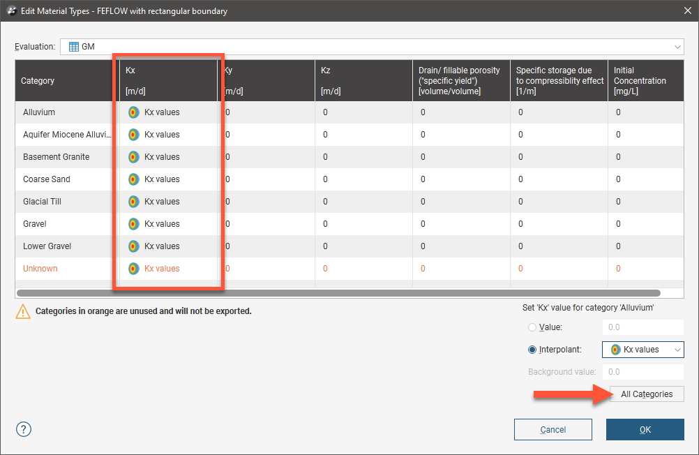
To use the interpolant for all the values in the selected column, click the All Categories button. The window will be updated to show that the interpolant values will be used for that column:
Click OK to update the grid.
Exporting FEFLOW Models
To export a 3D FEFLOW model as an ASCII format FEFLOW file (*.fem), right-click on the grid in the project tree and select Export To FEFLOW. You will be prompted to choose a File name and location. Select the options required, then click Save.
Whether the 3D FEFLOW model is exported as a flow only FEFLOW problem or as a flow and mass transport FEFLOW problem depends on the initial concentration values set in the Edit Material Types window.
- Flow only FEFLOW problem. If all the initial concentration values are 0, a flow only problem will be exported.
- Flow and mass transport FEFLOW problem. If at least one of the initial concentration values is set to a value other than 0, a flow and mass transport FEFLOW problem will be exported.
You cannot export 2D FEFLOW grids.