
MODFLOW Models
These features are only available as part of the Hydrogeology extension. See Flow Models for more information.
Once you have created a geological model, you can use it as the basis for a MODFLOW model. You can create both structured and unstructured MODFLOW models. You can also import existing MODFLOW models and assign lithologies from a geological model.
Steps for creating a MODFLOW model that can be exported and run outside Leapfrog Works are:
1. Create a geological model.
2. Create the MODFLOW model using the geological model to set the grid spacing and layers.
3. Evaluate the new model against a geological model, if it wasn’t when it was created.
4. Edit the hydrological properties.
5. Export the MODFLOW model to MODFLOW or Groundwater Vistas.
Once the model has been processed outside of Leapfrog Works, the model can be imported into Leapfrog Works and visualised in the scene.
Creating MODFLOW models in Leapfrog Works has the advantage that the resolution can be easily changed and the properties of the grid can be made to honour boundaries defined in geological models. Models created in Leapfrog Works can be evaluated against a geological model when they are created.
Once a model has been defined and evaluated against a geological model, hydrological properties can be assigned and the grid can be exported.
The rest of this topic describes working with MODFLOW models in Leapfrog Works. It is divided into:
- Importing a MODFLOW Model
- Structured MODFLOW Models
- Unstructured MODFLOW Models
- MODFLOW Evaluations
- Assigning an Evaluation for Export
- MODFLOW Hydrological Properties
- MODFLOW Model Display
- Setting a Dry Head Value
- Importing Head Values and MT3D Concentrations
- Generating a Head Value Mesh
- MODFLOW Model Export
Importing a MODFLOW Model
Leapfrog Works imports the following types of MODFLOW models:
- MODFLOW Name files (*.nam, *.mfi, *.mfn, *.modflow.in)
- MODFLOW Grid Specification files (*.gsf)
To import a MODFLOW model, right-click on the Flow Models folder and select MODFLOW > Import Model. Leapfrog Works will ask you to specify the file location, and then will display the data in the file in the Import MODFLOW Model window:
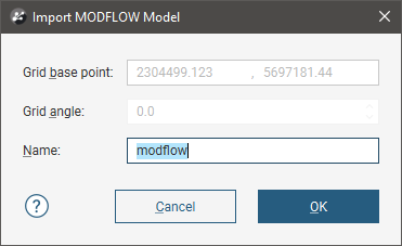
If the world origin is available, the Grid Position will be displayed but cannot be edited.
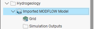
Click OK to import the grid. The new MODFLOW model will appear in the project tree in the Flow Models folder:
If the world origin was not available when the model was imported, you can change the Grid Position. To do this, double-click on its grid object (![]() ).
).
You can:
- Associate lithologies with the grid and then edit hydrological properties. Right-click on the model and select Evaluations. See MODFLOW Evaluations and MODFLOW Hydrological Properties.
- Set a dry cell head value and import head values and MT3D concentrations. See Setting a Dry Head Value and Importing Head Values and MT3D Concentrations.
- Once you have imported head values you can generate a head value mesh. See Generating a Head Value Mesh.
Structured MODFLOW Models
To create a structured MODFLOW model, you must first have at least one geological model defined in the project. Once this has been defined, add the geological model to the scene. Right-click on the Flow Models folder and select MODFLOW > New Structured Model.
The New MODFLOW Model window will be displayed, together with controls in the scene that will help you to set the grid extents:
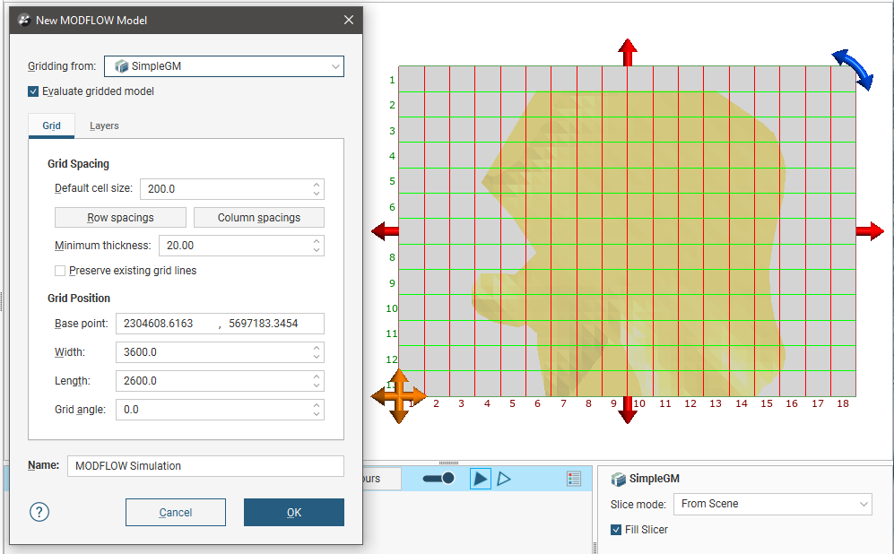
The new MODFLOW model will be based on the geological model in the Gridding from setting. If you wish to use a geological model other than the one selected when the window is opened, select it from the list. The grid dimensions will be updated in the scene.
If the Evaluate Gridded Model box is ticked, the selected geological model will be evaluated on the new grid and set as the evaluation for export. If you do not wish to evaluate the geological model on the grid, untick the box. You will still be able to use the layers in the geological model to control the grid layers.
The Preserve Existing Grid Lines option is used when setting a non-uniform grid in the scene window. If you are going to define a non-uniform grid in this way, create the model with the Default Cell Size set to the smallest cell size you wish to use, then edit it as described in Applying Varying Cell Sizes below.
The grid should be slightly smaller than the selected geological model. Any MODFLOW cells that exist outside the geological model will be marked as inactive when the grid is exported to MODFLOW .
Horizontal Grid Spacing
By default, the horizontal grid for the model is uniform, with the size of each cell set by the Default Cell Size value. You can change the horizontal grid by editing row and column spacings. When you click on Row Spacings or Column Spacings, the Edit Spacings window will be displayed:
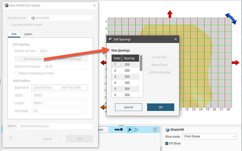
Changes made in the Edit Spacings window will be reflected in the scene.
There are four ways to change the spacings:
- Click on a value to edit it.
- Divide a row or column. Click on a row or column, then on the Divide Row or Divide Column button. Two new rows or columns will appear in the list.
- Merge rows or columns. Hold down the Shift key while clicking on each item, then click on the Merge Rows or Merge Columns button. The selected items will be combined.
- Set uniform spacing on selected rows or columns. You will be prompted to enter the number of cells you wish to create from the selected rows or columns.
Click OK.
For example, here, the rows and columns away from the model boundary have been divided to provide more detail. The different spacings are reflected in the scene:
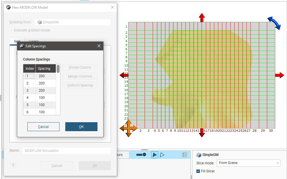
Use close spacing for steep gradients and increase or decrease spacing gradually.
Vertical Grid Layering
The vertical grid layers are based on the geological model selected in the New MODFLOW Model window. Click on the Layers tab to view the layers:
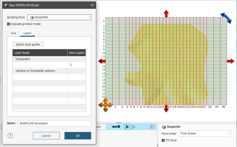
Initially, there are two layers equally spaced between the topography and the geological model. Change the layers by clicking on Select layer guides button. The Layer Guides window will appear, showing the layers available in the selected geological model:
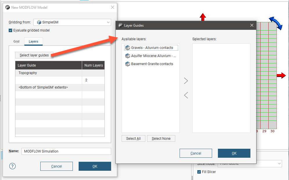
If the grid is required to follow a geological model lithology contact surface, move the layer into the Selected list and it will be honoured in the gridding process.
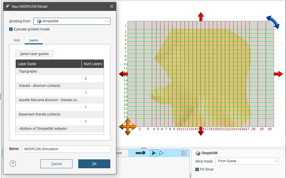
Click OK to return to the New MODFLOW Model window, in which the selected layers will be displayed:
Click OK to create the new MODFLOW grid, which will appear in the Flow Models folder. You can edit the model by expanding it in the project tree and double-clicking on the grid object (![]() ). The Edit MODFLOW Grid window will appear. You can edit the grid spacings, using the information in the scene window as a guide.
). The Edit MODFLOW Grid window will appear. You can edit the grid spacings, using the information in the scene window as a guide.
Applying Varying Cell Sizes
Another way to edit the grid is to use the controls in the scene to apply different cell size settings in different parts of the grid. For example, you may want to define a grid that has smaller cells in the centre than at the outer edges:
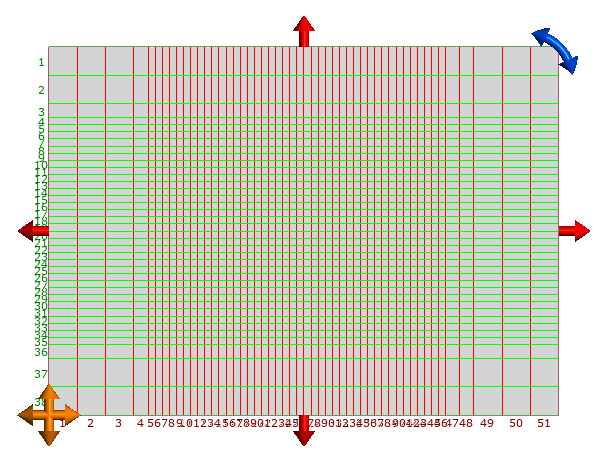
To set cell sizes in this way, it is best to start with a MODFLOW model where the New cell size is set to the smallest cell size you will use in the model.
For this example, we will start with a new grid with a New cell size of 50. We will set the adjacent cell size to 100 and the cell size at the outer boundary to 200.
First, we need to reduce the area that uses the cell size of 50 by using the red handles in the scene:
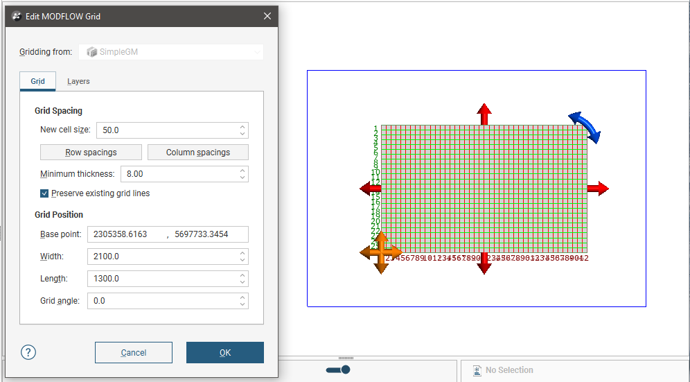
The blue box in the scene is the geological model extents for the model used to define the MODFLOW model and represents the unedited boundary of the MODFLOW model.
Next, enter the cell size to use for the area adjacent to the 50.0 cells in the New Cell Size field. Then, drag the red handles to enlarge the grid. The centre part of the grid is still set to 50, while the new area is set to 100:
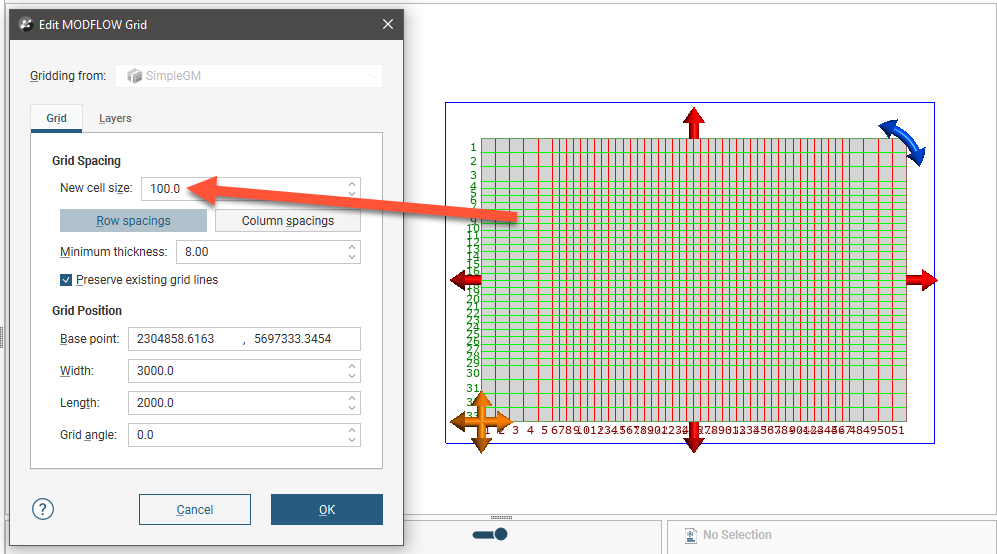
If the Preserve Existing Grid Lines option is enabled, grid lines for cells already defined will not be moved to account for new cells.
Enter the next cell size in the New cell size field and then use the handles to enlarge the grid again:
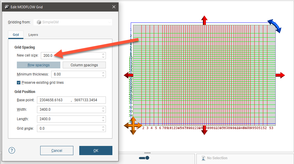
Click OK to update the grid.
Unstructured MODFLOW Models
To create an unstructured MODFLOW model, you must first have at least one geological model defined in the project. Once this has been defined, add the geological model to the scene. Right-click on the Flow Models folder and select MODFLOW > New Unstructured Model.
The New Unstructured MODFLOW Model window will appear. In this example, a geological model has been added to the scene to aid in defining the MODFLOW model:
The Gridding from setting determines the geological model used for layer guides. Ticking the Evaluate gridded model box will evaluate the new MODFLOW model against the selected geological model and set it as the evaluation for export. See MODFLOW Evaluations below for more information. If you do not wish to evaluate the geological model on the grid, untick the box. You will still be able to use the layers in the geological model to control the grid layers.
Once the model has been created, you can change most of its settings, but you will not be able to change the Gridding from model.
Click on the Layers tab to see the layers that will be used in the new model. By default, the layers from the Gridding from model are selected as layer guides, but you can change this by clicking the Select layer guides button and changing which layers are used:
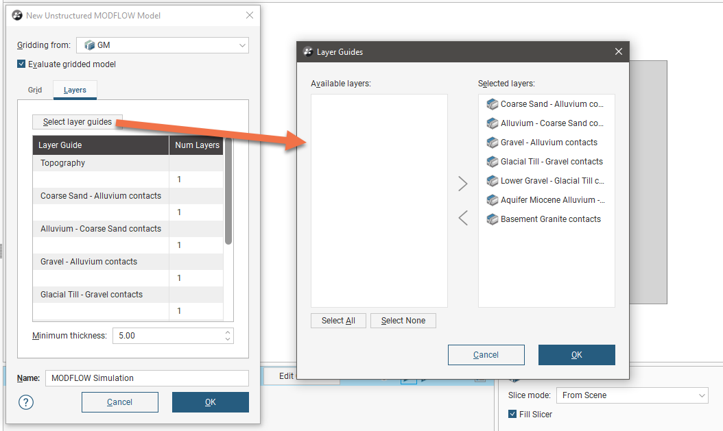
If the grid is required to follow a geological model lithology contact surface, move the layer into the Selected list and it will be honoured in the gridding process.
Once you have determined which layers you will use as layer guides, you can change how many layers there will be in the model. To do this, click on a layer in the Layers tab and edit the Num Layers value:
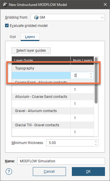
The minimum thickness of each layer is determined by the Minimum thickness setting in the Grid tab. If there is a conflict between the Minimum thickness setting and the number of layers defined in the Layers tab, Leapfrog Works will display an error message when you click the OK button to create the model.
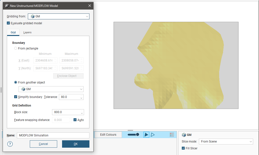
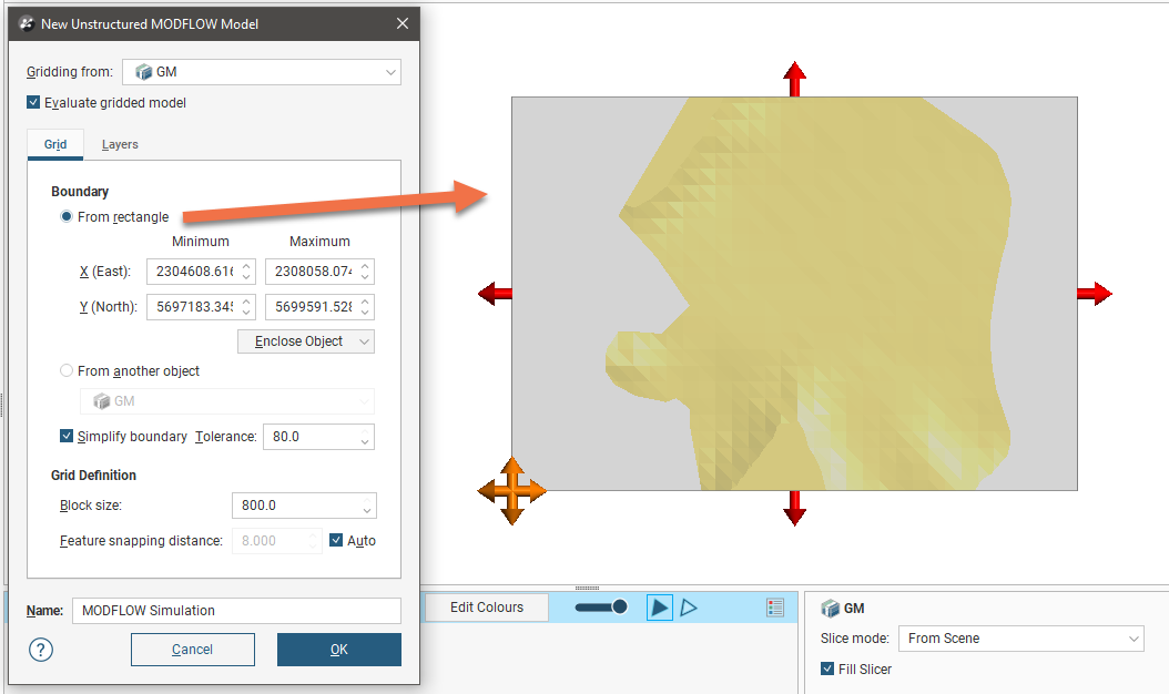
In the Grid tab, the model’s boundary can be defined as a rectangle or from another object in the project. In the example above, the geological model GM is used to define the MODFLOW model’s boundary. When the boundary is set to From rectangle, controls will appear in the scene that will help in setting the boundary:
The boundaries of the Gridding from model must be larger than the boundary of the new MODFLOW model.
When the boundary is set from another object in the project, the Simplify boundary option can be used to reduce the number of points along the boundary. A lower Tolerance value increases the number of points along the boundary. The two settings together let you define a basic boundary with blocks that are roughly uniform in size, set by the value of Block size. Here, a grid has been created from a geological model with the Simplify boundary option enabled:
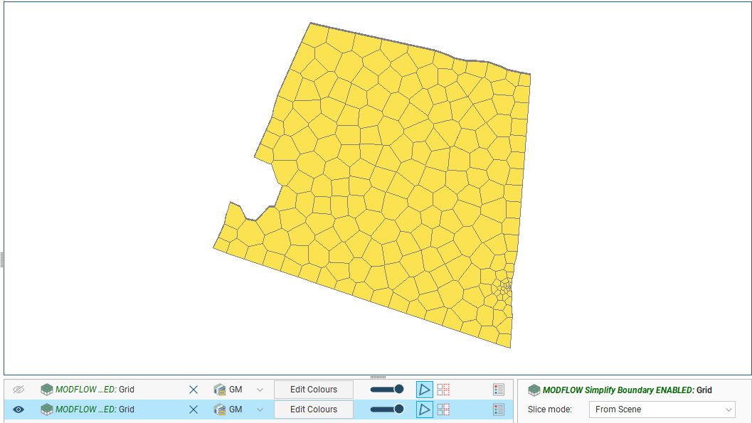
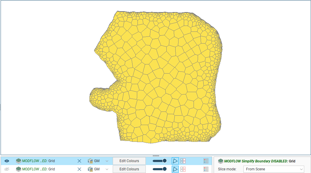
Disabling the Simplify boundary option results in more detail around the edges of the grid:
The Block size setting determines the basic size of the triangles that make up the grid, although the size will vary according to features applied to the grid and the Feature snapping distance. The size will also vary if the Simplify boundary option is unticked, in which case the Block size setting is the maximum size of the triangles.
The Feature snapping distance is automatically set to 1 percent of the Block size. To use a smaller snapping distance, untick the Auto box and set the value required.
Click OK to generate the new MODFLOW model, which will appear in the project tree under the Flow Models folder.
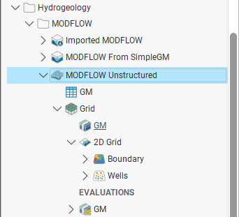
In the project tree, the MODFLOW model is organised into a 3D grid object (![]() ) that contains a 2D grid (
) that contains a 2D grid (![]() ):
):
To edit model settings such as the boundary, layer guides, Minimum thickness, Block size and the Feature snapping distance, double-click on the 3D grid object (![]() ). The geological model used for gridding cannot be changed.
). The geological model used for gridding cannot be changed.
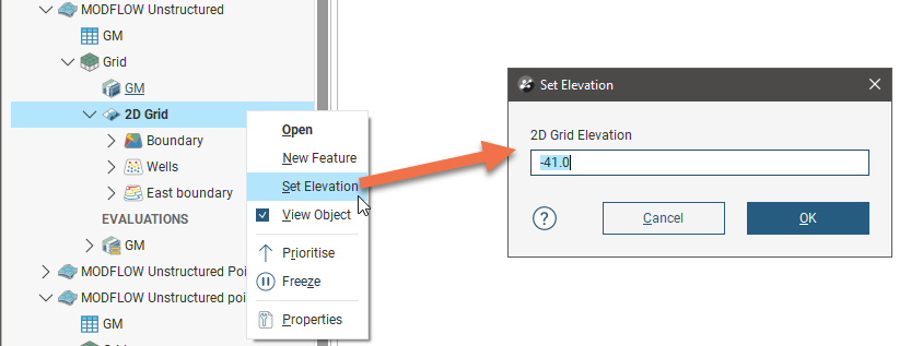
You can change the elevation of the 2D grid, if required. To do this, right-click on the grid and select Set Elevation:
You can refine the resolution of the model by adding features to it around objects about which you have more information, such as drilling data.
To add features to the model, expand it in the project tree, then right-click on the 2D grid object (![]() ) and select New Feature.
) and select New Feature.
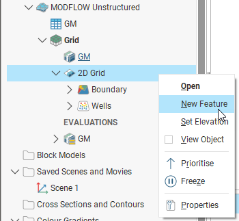
In the window that appears, you can add points, lines and polygons to the model. Click the Select button to view the objects in the project that can be added to the model. If an object has query filters defined, you can filter the data, if required.
Select the object you wish to use, then click OK to return to the New MODFLOW Feature window.
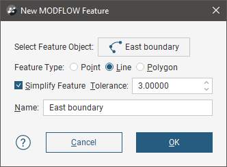
For many objects, the Feature Type setting will be automatically determined, but for polylines, you can select the Feature Type.
Ticking the Simplify Feature option will reduce the number of points used, with a lower Tolerance value increasing the number of points along the boundary.
Once you have added a feature to the grid, you can edit the Simplify Feature/Tolerance settings, but you cannot change the object used or switch to a different query filter.
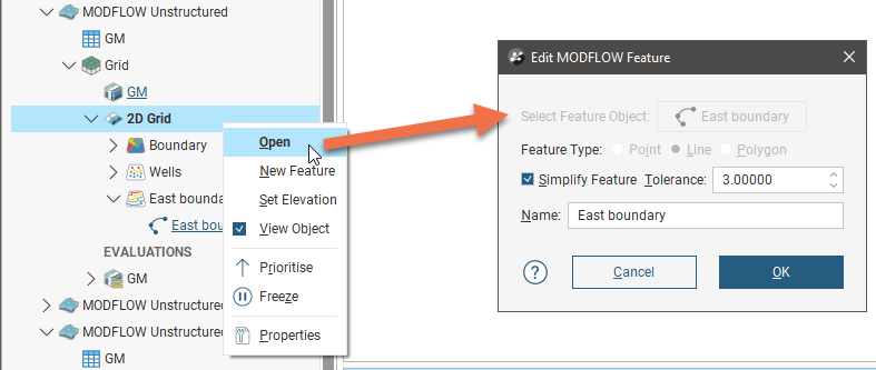
Click OK to add the feature, which will appear in the project tree under the 2D grid object:
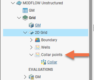
You can edit the feature by double-clicking on it or by right-clicking on it and selecting Open. In the Edit MODFLOW Feature window, you can enable or disable the Simplify Feature setting and change the Tolerance.
To view all features that have been applied to a MODFLOW model, double-click on the 2D grid object (![]() ). This opens the Edit 2D MODFLOW Unstructured Grid window with the Features tab open, showing all features that have been added to the grid:
). This opens the Edit 2D MODFLOW Unstructured Grid window with the Features tab open, showing all features that have been added to the grid:
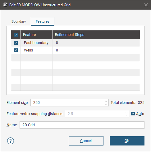
You can set Refinement Steps on a feature-by-feature basis. More steps will produce more detail near the feature.
If you want to modify a feature without having to reprocess the grid, untick it in the Features tab. If you want to delete a feature, right-click on it in the project tree and select Delete.
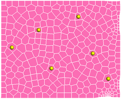
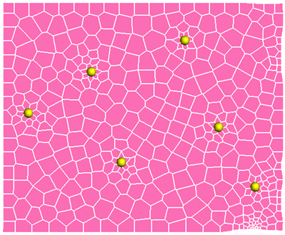
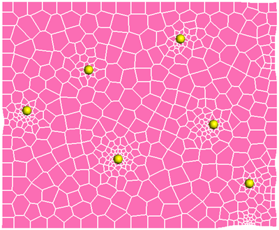
The images below show a grid displayed with collar points (in yellow) to demonstrate the effects of no features and collars applied with different refinement steps:
|
|
|
| No features | Collar points with 2 refinement steps | Collar points with 10 refinement steps |
MODFLOW Evaluations
When a MODFLOW model is exported, the evaluated geological model is used to assign lithologies to the cells in the grid. If the grid has not been evaluated against a geological model, you must do so before you can edit the hydrological properties and before you can export the grid.
To evaluate a MODFLOW model, right-click on the model in the project tree and select Evaluations. Although you can evaluate an interpolant or distance function, they cannot be exported with the grid and are simply used for displaying the grid in Leapfrog Works.
A window will appear listing all objects in the project that can be used for an evaluation. Once you have selected one or more objects, click OK. You will then be able to select the evaluations from the view list, as described in Evaluations.
Assigning an Evaluation for Export
For MODFLOW models created in Leapfrog Works, the evaluation used when creating the model will automatically be assigned as the evaluation for export. A hydrological properties table (![]() ) will appear in the project tree as part of the model.
) will appear in the project tree as part of the model.
If the model was imported into Leapfrog Works or created without being evaluated against a geological model, you will need to manually set the evaluation for export. To do this:
- Evaluate the grid against one or more geological models, as described above.
- Right-click on the model in the project tree and select Set Evaluation for Export. The Select Evaluation window will appear showing all geological models evaluated on the grid. Select the required evaluation and click OK.
A hydrological properties table will be added to the model in the project tree. Edit hydrological properties by double-clicking on the table.
MODFLOW Hydrological Properties
MODFLOW models created in Leapfrog Works have a hydrological properties table (![]() ) based on the geological model used as the basis for the MODFLOW model. You can edit hydrological properties by double-clicking on the table. You can also open the table by right-clicking on the model in the project tree and selecting Edit Hydrological Properties.
) based on the geological model used as the basis for the MODFLOW model. You can edit hydrological properties by double-clicking on the table. You can also open the table by right-clicking on the model in the project tree and selecting Edit Hydrological Properties.
If the model has been imported into Leapfrog Works and has not yet been evaluated against a geological model, you will first need to evaluate a geological model on the MODFLOW model. To do this, expand the model in the project tree, right-click on the grid object and select Evaluations. See MODFLOW Evaluations for more information.
Hydrological properties are assigned to model blocks based on the position of the block’s centroid relative to the geological model used to evaluate the grid. The position of the centroid is calculated and Leapfrog Works then determines which lithology the centroid falls inside. The K values for the assigned lithology are assigned to the entire block; there is no averaging.
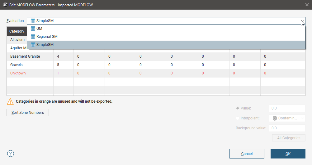
If more than one object has been evaluated on the grid, you can set hydrological properties separately for each evaluation. Select the required evaluation from the Evaluation list:
However, the only hydrological properties information that will be exported is that set for the evaluation to be exported.
Setting Hydrological Properties
In the Edit MODFLOW Parameters window, you can enter the values for hydrological properties manually or you can use the values from an interpolant.
To enter values manually, click on a cell, then enter the value in the Value field:
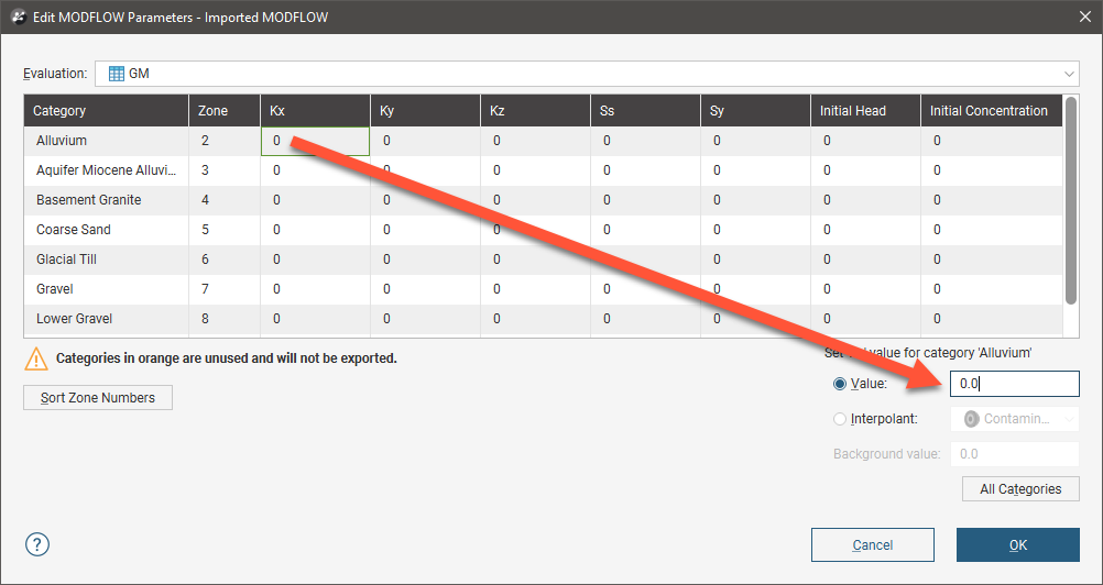
Press the Enter key to move down the columns.
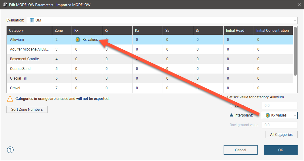
To use the values from an interpolant, click the Interpolant button, then select an interpolant from the list. The interpolant that will be used for the selected value will be displayed in the field:
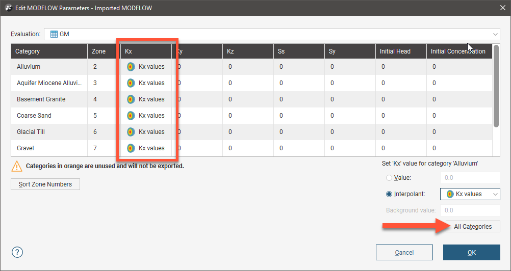
To use the interpolant for all the values in the selected column, click the All Categories button. The window will be updated to show that the interpolant values will be used for that column:
Zone Numbers
When the model is exported, the zone numbers are used to indicate the assignment of lithologies to blocks and are written to the MODFLOW zoned layer properties flow (*.lpf) file. In the Edit MODFLOW Parameters window, you can change the zone number for a lithology by clicking in a cell and entering a different zone number. If you reorder the zones in this way, zone number conflicts will be highlighted in red:
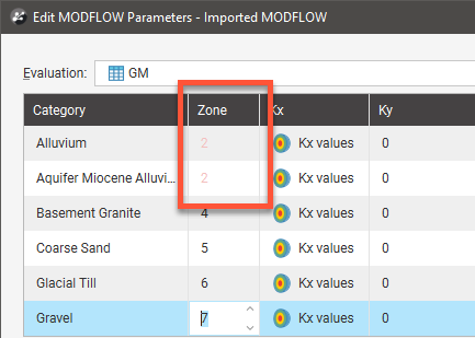
Zone numbers must be unique and you will not be able to close the window and save data if there are conflicts.
If you click on the Sort Zone Numbers button, the zone numbers will be ordered from top to bottom.
Zone numbers should not be sorted once a model has been exported as the new numbers will not be reflected in the exported model.
Click OK to update the grid.
MODFLOW Model Display
If you do not have the Hydrogeology extension, MODFLOW models will appear in the project tree as Restricted. You can display them in the scene, but you cannot modify them.
In the project tree, MODFLOW models are made up of a grid object (![]() ), a Simulation Outputs folder and a hydrological properties table (
), a Simulation Outputs folder and a hydrological properties table (![]() ) object. If there is no hydrological properties table, an evaluation has not yet been set for export. See MODFLOW Evaluations for more information.
) object. If there is no hydrological properties table, an evaluation has not yet been set for export. See MODFLOW Evaluations for more information.
For MODFLOW models created in and imported into Leapfrog Works, dragging the model itself into the scene will display the grid (![]() ) object. The different parts of the model can also be displayed.
) object. The different parts of the model can also be displayed.
Dragging a MODFLOW model into the scene displays its grid object. Here, an imported model has been evaluated against a geological model and added to the scene:
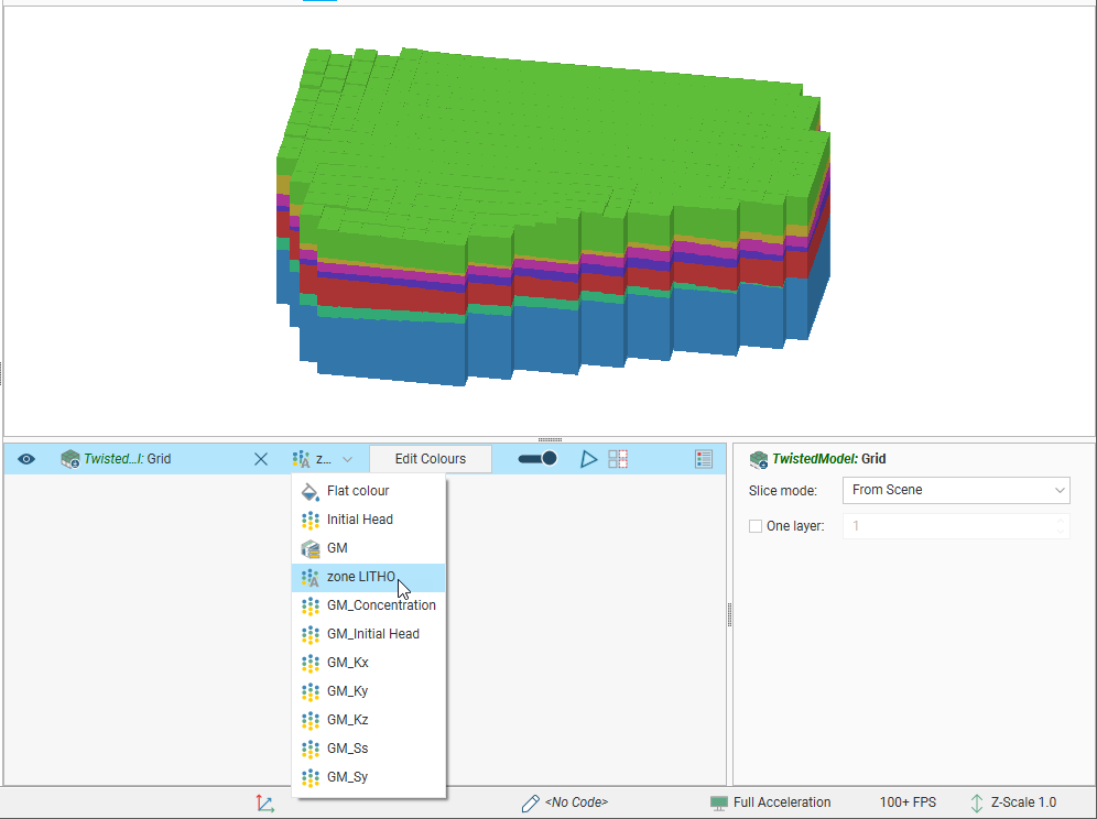
The viewing options available are the flat colour option, the evaluated geological model and zone data imported with the model. Other inputs imported with a model will also be available from this list, and once the model has been evaluated against a geological model or interpolant, you can also display the model using the grid’s hydrological properties.
Grids are displayed as cells. When a geological model evaluation or lithological zone information is displayed, you can also display a legend for the grid.
When Show edges(![]() ) is enabled, the edges of the cells will be displayed.
) is enabled, the edges of the cells will be displayed.
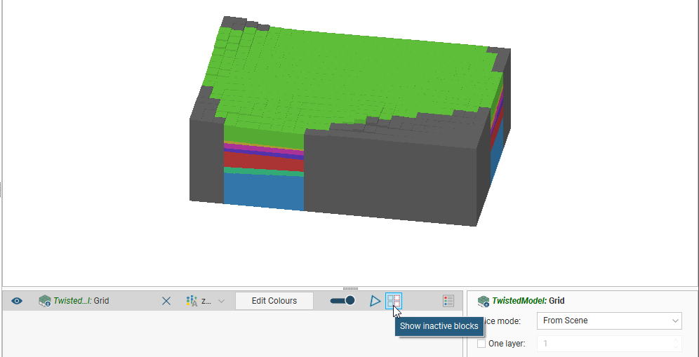
The Show inactive blocks(![]() ) option displays inactive cells in grey:
) option displays inactive cells in grey:
To display a single layer, tick the One layer box in the shape properties panel, then select the layer to display.
Head values and MT3D concentrations can also be imported and displayed. See Importing Head Values and MT3D Concentrations.
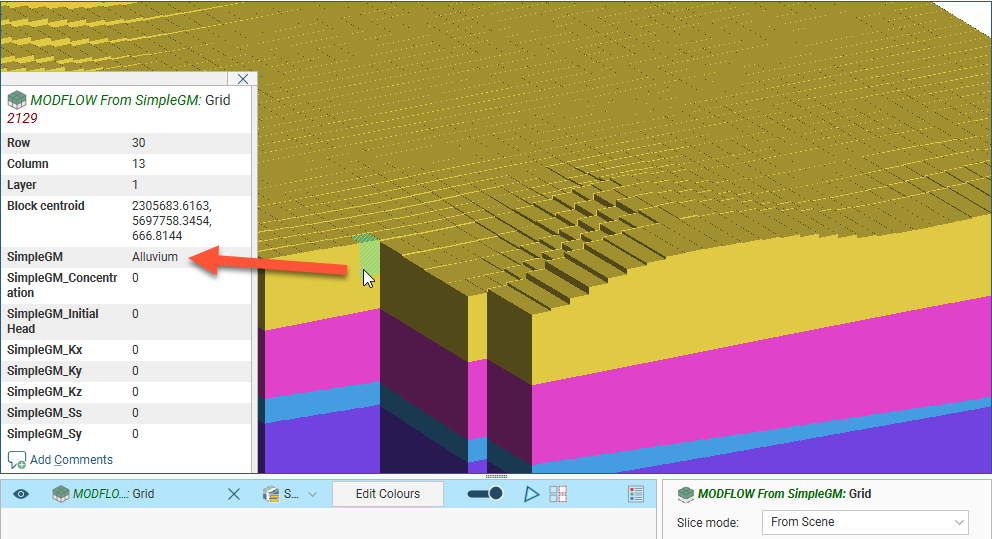
When a MODFLOW model is displayed in the scene, you can view information about the individual cells in the model by clicking on a block. The window that appears shows information about the selected block, including its centroid and the lithology assigned to the block from the evaluated geological model. Information from all geological models and interpolants the grid has been evaluated against will be displayed:
Setting a Dry Head Value
You can set a dry cell head value and matching head values imported onto the MODFLOW model will be ignore. To set a dry head value, right-click on a MODFLOW model’s 3D grid object (![]() ) and select Set Dry Head Value.
) and select Set Dry Head Value.
In the window that appears, set a value, then click OK.
Note that this value is used when heads are imported; changing the value in this window has no effect if head values have already been imported.
Importing Head Values and MT3D Concentrations
Leapfrog Works imports the following output file formats:
- Head values files in *.hds, *.hhd and *.hed formats
- MT3D concentrations files in *.ucn and *.con formats
Before importing head values, you may wish to set a dry cell head value. To do this, right-click on the model’s 3D grid object (![]() ) and select Set Dry Head Value.
) and select Set Dry Head Value.
To import head values or MT3D concentration files for a MODFLOW model, right-click on the Simulation Outputs folder and select the required option. Navigate to select the file, then click Open.
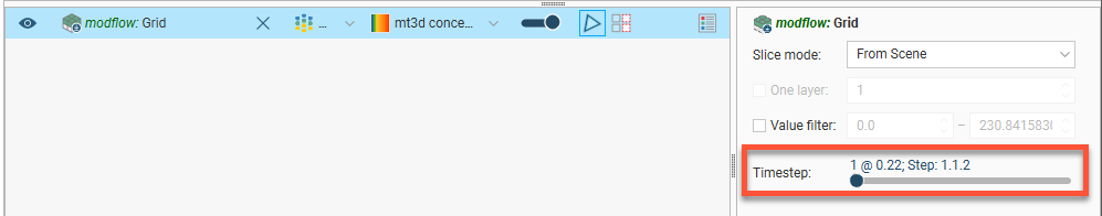
The information will be added to the MODFLOW grid, and you can then select the head values and MT3D concentrations in the shape list when you display the grid in the scene. If the output is time-dependent, a timestep slider will be available from the shape properties panel. Click and drag the slider or click along the timeline to view the different timesteps available:
Imported head values and MT3D concentrations are stored in the project tree in the Simulation Outputs folder. To delete head values or MT3D concentrations, right-click on the object in the project tree and select Delete.
Once head values have been imported, you can generate a head value mesh.
Generating a Head Value Mesh
Once head values have been imported for a MODFLOW model, you can generate a head value mesh. To do this, expand the Simulation Outputs folder. Right-click on the head values object and select Generate Head Value Mesh. The Generate Head Value Mesh window will appear, showing the layers in the model and the timesteps available. Select the layer of the model you wish to generate a head value mesh for, then choose the heads. Click OK to create the mesh, which will be saved to the Meshes folder.
MODFLOW Model Export
Leapfrog Works has the following options for exporting MODFLOW models:
- Export the grid as a MODFLOW file.
- Export for Groundwater Vistas. Use this option the first time you export a grid for use in Groundwater Vistas.
- Export a Groundwater Vistas update. Use this option to generate a set of files that can be imported into Groundwater Vistas as an update.
- Export the grid’s hydrological properties in *.csv format.
The Groundwater Vistas options include a zoned layer properties flow (*.lpf) file that includes information about the zones in the grid.
The options available differ for imported models, structured models created in Leapfrog Works and unstructured models created in Leapfrog Works.
| Imported | Structured Models | Unstructured Models | |
|---|---|---|---|
| Export to MODFLOW in MODFLOW USG format |
|
|
|
| Export to MODFLOW in MODFLOW 6 format |
|
|
|
| Export to MODFLOW for Groundwater Vistas |
|
|
|
| Export to GWV Updates |
|
|
|
| Export Hydrological Properties |
|
|
|
As a MODFLOW File
To export a grid as a MODFLOW file for use in a package other than Groundwater Vistas, right-click on the grid in the project tree and select Export to MODFLOW.
For unstructured models created in Leapfrog Works, two formats are supported:
- MODFLOW USG Name Files (*.nam)
- MODFLOW 6 Name Files (*.nam)
For structured models created in Leapfrog Works and imported MODFLOW models, only MODFLOW USG format is supported.
You will be prompted to choose a File name and location. Select the options required, then click Save.
For Groundwater Vistas
To export a grid for use in Groundwater Vistas for the first time, right-click on the grid in the project tree and select Export to MODFLOW for GWV. You will be prompted to choose a File name and location. Select the options required, then click Save.
If you have previously exported the grid to Groundwater Vistas and have made changes to the grid, use the Export to GWV Updates option.
As a Groundwater Vistas Update
If you have exported a grid to Groundwater Vistas but then make changes to the Leapfrog Works model, you can export the changes to the model. The set of files containing the changes can then be imported to Groundwater Vistas.
To export a Groundwater Vistas update, right-click on the grid in the project tree and select Export GWV Updates. The Update Groundwater Vistas window will appear listing the files that will be exported. Enter a Base file name to differentiate the original files from the updates. Click Export. The files will be saved in the specified directory.
Export Hydrological Properties
To export a grid’s hydrological properties in *.csv format, right-click on the grid in the project tree and select Export Hydrological Properties. In the window that appears, select where you wish to save the file, then click Save.
The exported file can be imported into AquaVeo GMS as a dataset.