Drawing Slices in the 3D Scene
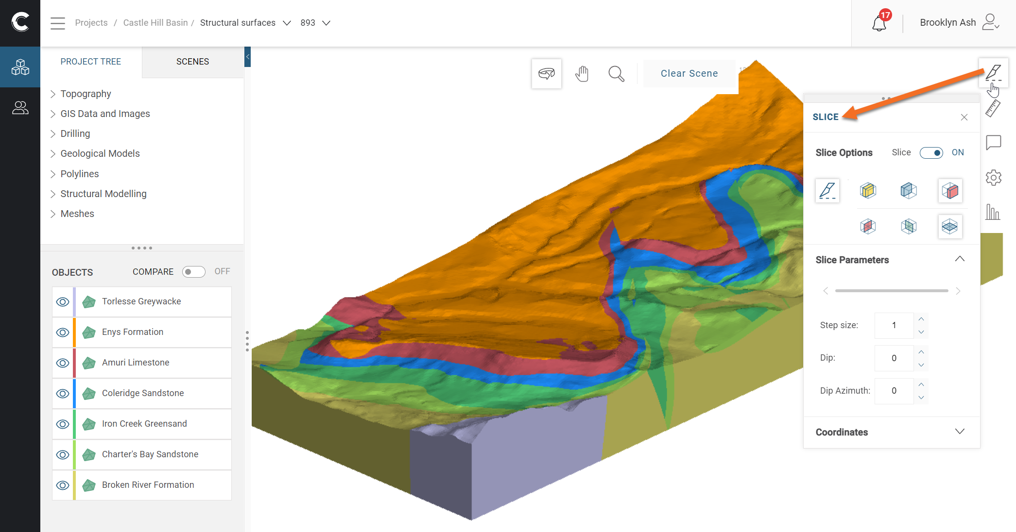
This guide describes how to use the Slicer tool (![]() ) to cut cross-sectional views through your data and models. This tool can be found in the tool strip on the right-hand side of the 3D scene:
) to cut cross-sectional views through your data and models. This tool can be found in the tool strip on the right-hand side of the 3D scene:
For an introduction to working in the 3D scene, see the Visualising Data in the Central Portal guide.
Click the Slicer tool (![]() ) to open the Slicer panel, then click on the Draw slice button (
) to open the Slicer panel, then click on the Draw slice button (![]() ) and draw in the scene to set your initial slice:
) and draw in the scene to set your initial slice:

Use the following keyboard shortcuts in working with the slicer:
- To centre the slicer in the scene, press the C key.
- To move the slicer in the scene, hold down the Ctrl key and the right mouse button while moving the mouse.
- To change the slice width, hold down the Ctrl key and both mouse buttons while moving the mouse.
- To look at the slicing plane, press the L key.
- To look at the back of the slicing plane, press Shift+L.
- To orient the slicer to the current view, press Ctrl+V.
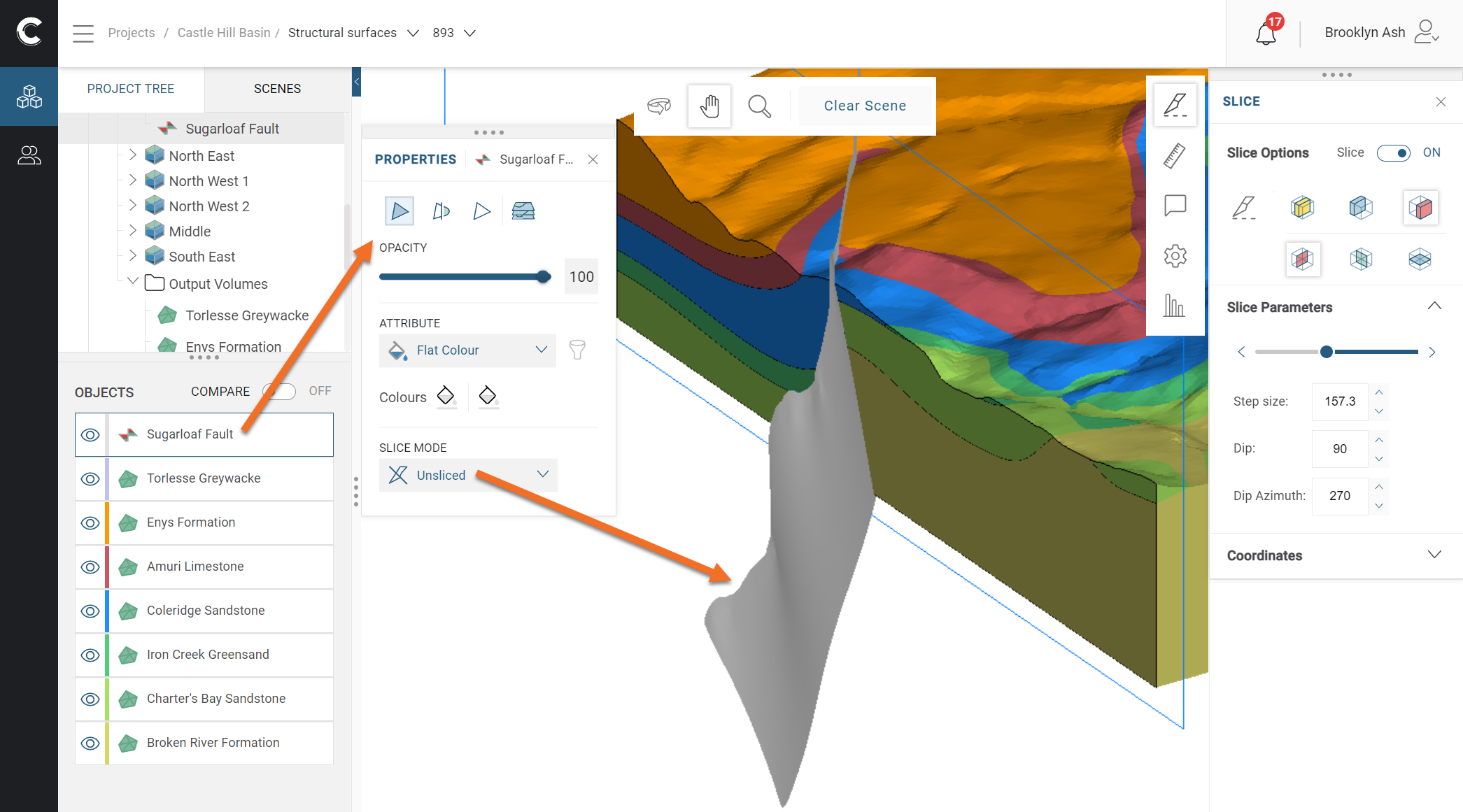
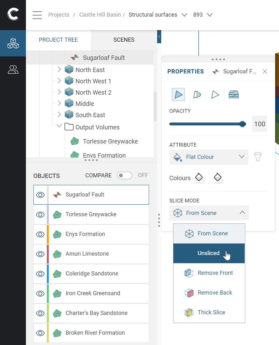
Each object has a Slice Mode property that determines how it is displayed when the slicer is in the scene:
This is useful for seeing relationships between objects.
When set to From Scene, an object is displayed using the slicer’s settings. This is the default used when an object is added the scene, but the other Slice Mode options can be useful in showing how a model has been constructed. For example, here model volumes are shown sliced, with the slicer line in blue. The fault is unsliced so we can see how the fault surface intersects with the model volumes: