Editing Vein Segments
When veins are created from drilling data, vein segments are categorised into hangingwall segments, footwall segments or excluded segments. In some circumstances, internal segments are also supported.
How each type of segment is used in building the vein is as follows:
- The endpoints of the hangingwall and footwall segments are used to create the initial hangingwall and footwall surfaces.
- Excluded segments are those that are completely enclosed within the vein lithology and so do not have hangingwall or footwall contact points. They have no influence on the vein geometry, but can be manually edited if they are understood to be hangingwall, footwall or internal segments.
- Internal segments force the hangingwall and footwall surfaces away from these segments. Internal segments arise from adding other contacts to the vein or from manually categorising segments. Classifying some segments as internal can be useful in scenarios where the vein boundary does not intersect the sample area, such as when the vein lithology flows in and around the sampled area.
This topic describes different methods for changing how Leapfrog Energy generates vein segments from drilling data. These are:
Changing Vein Segment Settings
When a vein is created from drilling data, there are settings that determine:
- How intervals at the ends of wells are handled when generating vein segments and midpoints
- Whether the vein boundary intersects any given well multiple times
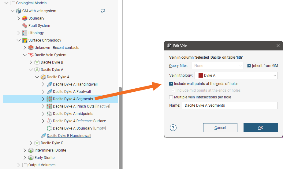
Each of these settings are available when a vein is first created. For existing veins, these settings can also be changed by double-clicking on the vein segments object ( ) in the project tree. This opens the Edit Vein window:
Include Wall Points at Ends of Holes
The Include wall points at the ends of holes setting determines whether or not hangingwall and footwall contact points are generated for segments at the ends of wells. If this setting is disabled, a contact point will not be created when a well ends in the vein lithology.
You can see the effects of the Include wall points at the ends of holes setting here where the hangingwall (red) and footwall (blue) points are displayed alongside the vein lithology intervals (in pink), the well traces and the resulting vein surface. In the first example, Include wall points at the ends of holes is disabled. Hangingwall points are not generated at the ends of the wells where indicated and so there isn’t enough data to build the vein surface:
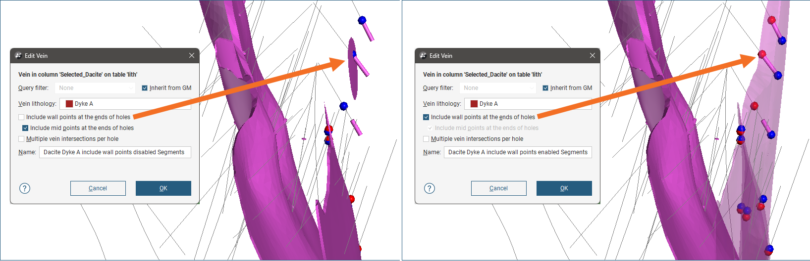
In the second example, Include wall points at the ends of holes is enabled, hangingwall contact points are created and the vein surface that results is much more realistic.
Whether to enable or disable Include wall points at the ends of holes depends on your data. Consider disabling Include wall points at the ends of holes if:
- A vein is being prematurely truncated
- A vein is blowing out unrealistically
Include Midpoints at Ends of Holes
The Include mid points at the ends of holes affects how the midpoints are generated when vein lithology segments occur at the start or end of wells. When Include mid points at the ends of holes is disabled, the midpoints are still generated but are automatically excluded. In these examples, there are three segments where wells end with the vein lithology. On the left, Include mid points at the ends of holes is enabled and there are no excluded midpoints; all the midpoints are shown in green.
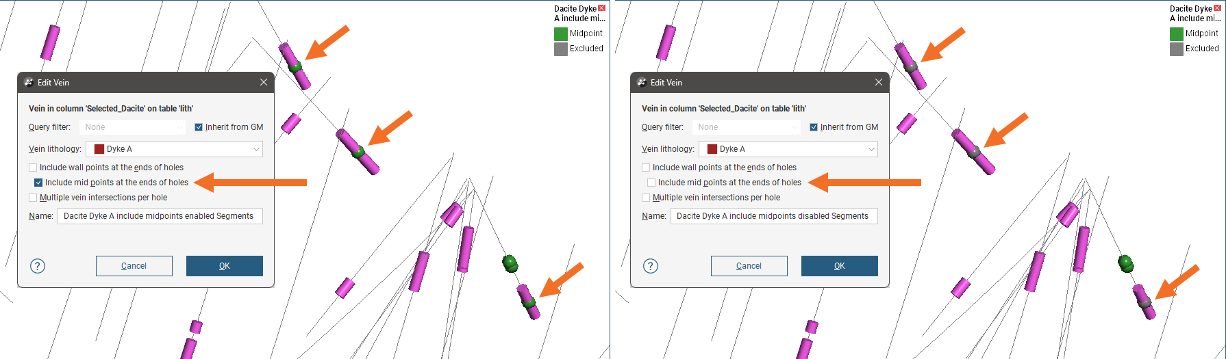
On the right, midpoints at the ends of holes are not included and so are shown in grey (Excluded).
Consider disabling the Include mid points at the ends of holes setting if your reference surface is “wiggly” or otherwise showing unexpected distortions.
To change the settings in this window for an existing vein, expand the vein in the project tree and double-click on the vein segments ():
Multiple Vein Intersections Per Hole
The Multiple vein intersections per hole setting is useful situations where wells might pass in and out of the same vein unit multiple times. Here a folded vein is shown with Multiple vein intersections per hole disabled (left) and enabled (right):
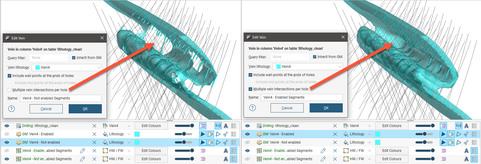
Note that for folded veins, you may also need to edit the vein’s reference surface and manually edit the vein segments to achieve a realistic surface. See:
- The separate Editing the Vein Reference Surface topic
- Editing Vein Segments in the Scene later in this topic
Editing Vein Segments in the Scene
When veins are created from drilling data, vein segments are categorised into hangingwall segments, footwall segments or excluded segments. A fourth category, internal segments, is also supported.
If you need to change the categorisation of individual vein segments, you can do this by right-clicking on the vein segments object () in the project tree and selecting Edit In Scene.
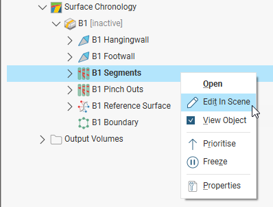
If you manually edit vein segments, you can export the edits for use in other veins and models in the current project or in other projects. The edits are exported in a text file. See the Exporting and Importing Vein Edits topic for more information.
If the vein segments object is already in the scene, you can edit it by clicking the Edit button ( ) in the shape list:
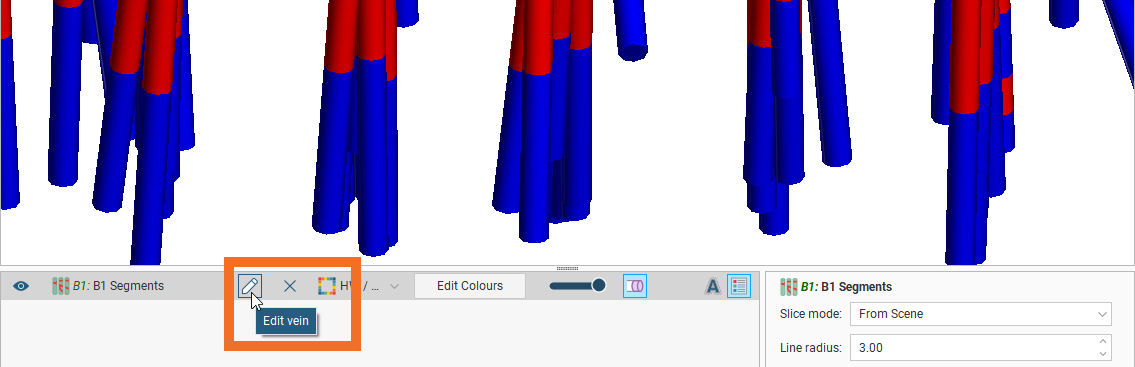
The Vein Segments window will appear, along with a set of tools for selecting segments in the scene:
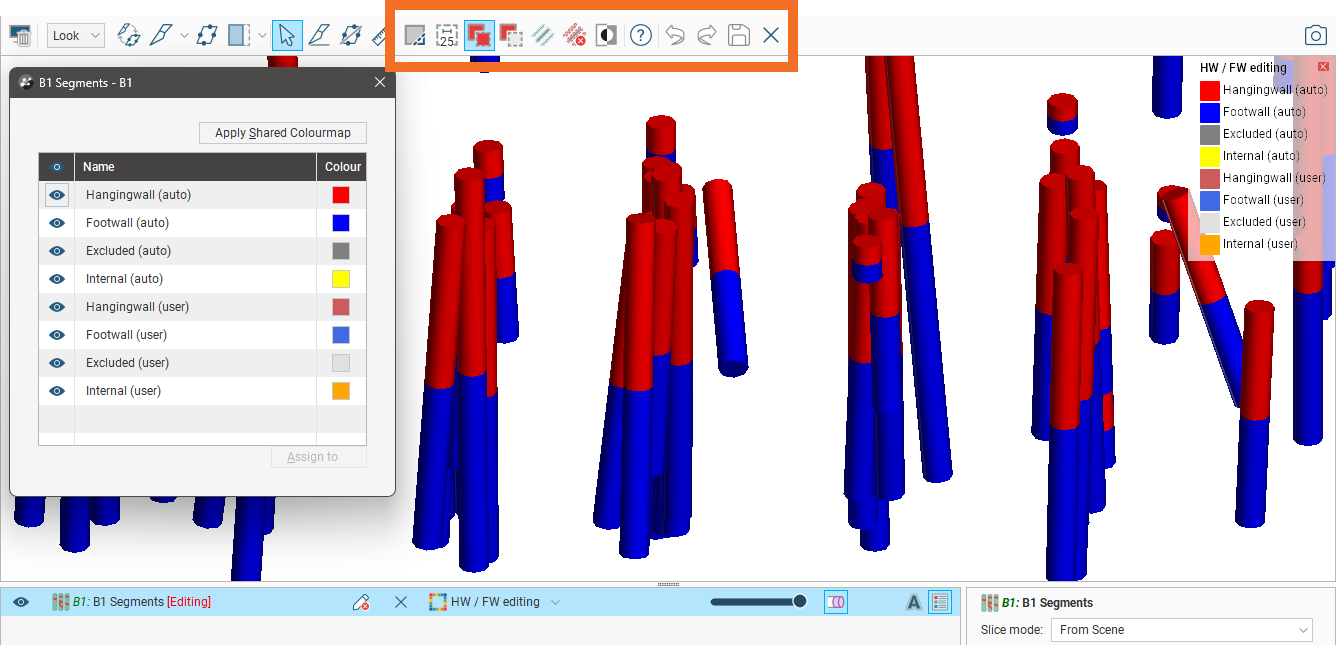
To select segments, click on the Select segments button ( ) and click the Add segments button (
 ). In the scene, draw a line across each segment you wish to select:
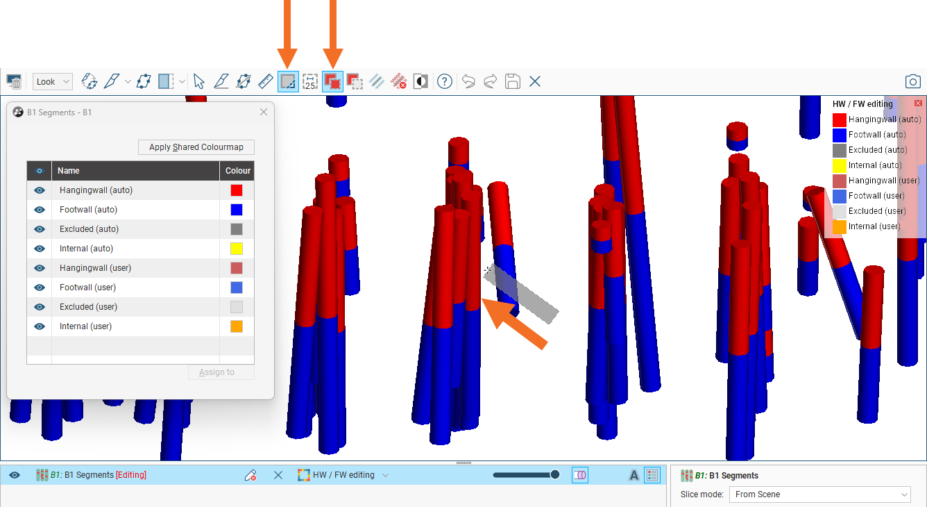
Selected segments are highlighted in the scene. If you accidentally select the wrong segment, either:
- Click the Remove segments tool (
 ) and draw across the point once again.
- Hold the Ctrl key while drawing across the point.
You can also:
- Select all visible segments by clicking on the Select all tool (
 ) or by pressing Ctrl+A.
- Clear all selected segments by clicking on the Clear selection tool (
 ) or by pressing Ctrl+Shift+A.
- Swap the selected segments for the unselected segments by clicking on the Invert selection tool (
 ) or by pressing Ctrl+I.
To change the width of the line used to select segments, click on the Change line width button ( ) and enter a new value. You can keep the Set Line Width window open while you select intervals so you can change the line width as required:
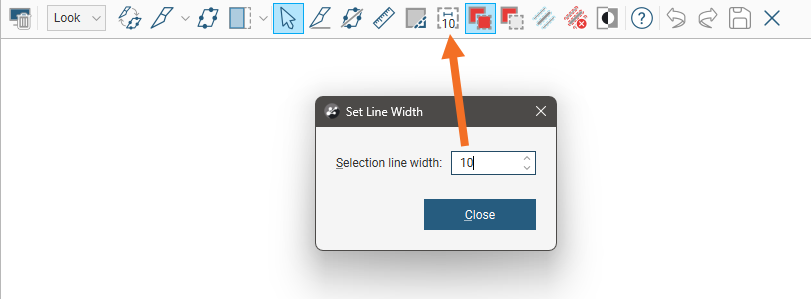
Note that the current line width is indicated by the Change line width button.
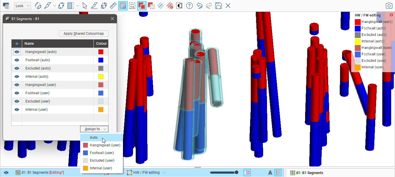
When you have selected at least one segment, click on the Assign to button, then select the category you want to assign the selected segments to:
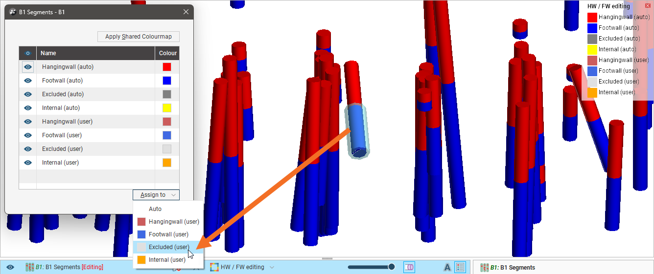
The categories shown for vein segments are:
- Hangingwall (auto), Footwall (auto) and Excluded (auto). These are the categories Leapfrog Energy assigned segments to when the vein was created.
- Hangingwall (user), Footwall (user) and Excluded (user). Segments assigned to these categories have been manually assigned to these categories. These are the categories you can assign selected segments to.
Assigning a segment to the Auto category sets it to the category Leapfrog Energy automatically assigned it to when the vein was created, which has the effect of undoing any edits made previously.
You can change the colours if you wish, but note that when the segments are displayed in the scene, the default colours make it easy to differentiate between automatically-categorised segments and those that have been edited.
The selected segments will be updated to reflect the change:
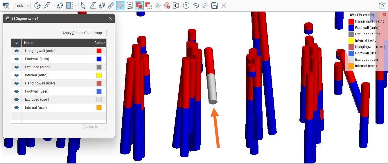
Click the Save button ( ) to view the effect of the changes.
To revert to the categories assigned by Leapfrog Energy when the vein was created, select some segments and then assign them to the Auto category: