
Defining zones
Local ellipsoids identified by Driver can be used to create 3D wireframes that delineate the spatial extents of continuity. These are called zones. Zones are useful for testing spatial hypotheses, making comparisons and iterating using different thresholds.
The zone identification algorithm in Driver uses a locally varying anisotropy (LVA) estimation combined with an isosurface extraction procedure to identify spatial volumes within the dataset. It operates similarly to a numeric model in Leapfrog Geo, with the addition of several automated procedures applied in order to enhance the LVA continuity, minimise blowouts and optimise the mesh quality and surface resolution. By being directly connected with the anisotropy estimations, zones can automatically adapt to local changes in the deposit geology and form a geologically meaningful view on the deposit geometry.
The rest of this topic describes
Creating zones
To create a new zone, right-click on the Zones folder in the project tree and select Create zones from anisotropy.
In the window that appears, select the anisotropy analysis to create the zone from, here the anisotropy analysis AU_PPM_vein_clusters is selected. The Name suffix of _z is given but this can be changed. Each zone created will also automatically be labelled with the chosen analysis. In this example, the complete name would be AU_PPM_vein_clusters_z.
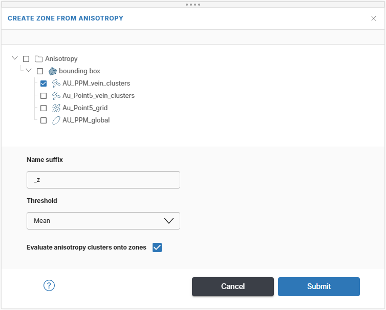
Choose the threshold you would like to create zones at (iso-value). Driver will automatically determine an appropriate mesh resolution and create the output wireframe.
Click Submit to start the estimation. Progress is shown in the project tree and in the processing queue.
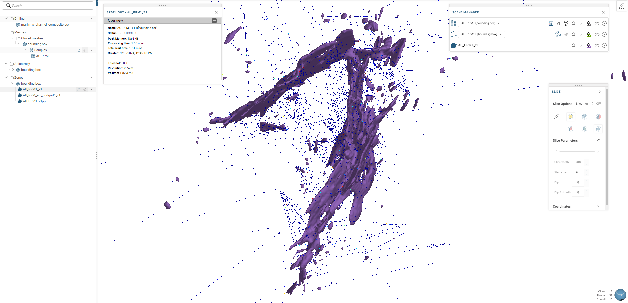
Once the zone has finished processing it, you can display it in the scene. For example, here 3D zone is displayed in the scene that delineates the spatial extent of grade continuity above 0.9ppm:
Publishing and exporting zones
Zone objects are 3D wireframes and can be published to the Driver project’s Evo workspace or downloaded to your local hard drive.