
New GM-SYS Model from a Map Profile
Run the GMSPROF GX to create a GM-SYS Profile Modelling model from a profile defined interactively on the current map window. You can specify source grids containing gravity and/or magnetic data, observation elevations, and topography in the initial dialog. A second dialog enables you to extract up to 15 horizons from grids for inclusion in the model. A third dialog enables you to specify grids containing observed gravity and/or magnetic gradient data. GM-SYS Profile Modelling is then launched to model the data.
The option is also available in Project Explorer from the context menu GM-SYS 2D Models > New GM-SYS 2D Model > From Map Profile.
New GM-SYS Model from a Map Profile dialog Options
|
Model name |
The name of the output GM-SYS Profile Modelling model. |
|
Magnetic grid |
Total magnetic field grid (nT). |
|
Magnetic elevation grid OR |
Magnetic field observation elevation grid. |
|
constant magnetic elevation |
Constant magnetic observation elevations; only used if no grid is specified for the magnetic elevations. Either Bouguer or free-air anomaly grid (mGal). |
|
Gravity grid |
Use either Bouguer or free-air anomaly (mGal). |
|
Gravity elevation grid OR |
Gravity observation-elevation grid (+ up). |
|
constant gravity elevation |
Constant gravity observation elevation; only used if no grid is specified for the gravity observation elevations. Defaults to Observation Elevation from current 3D model. |
|
Topography grid OR |
Topography elevation grid (+ up). |
|
constant topography elevation |
Constant topography elevation; only used if no grid is specified for the topography. |
|
Vertical Distance units |
Choose the vertical distance units from the list. All elevations and depths must be expressed in these units. |
|
Number of points in profile |
The maximum number of points to use in the model profile. If the data profile has fewer points, the data is used as selected. If the data profile has more points, the profile will be resampled to the maximum points specified here. The standard version of |
|
Method to set profile coordinates |
Select method to set profile coordinates: "digitizing" or "manual input". Profiles may be defined interactively, using the digitizing tool, or manually, by specifying up to 5 X and Y positions. In the digitizing option, left-click at each point to select a location; right-click and select "done" to complete the profile definition. |
Horizons Options
Horizon grid(s)
|
Horizon Values are… |
All horizon grids must be either elevations (+UP), depths (+DOWN), or two-way travel time in seconds (+DOWN). Select the proper mode from the list. |
|
Horizon 1 grid |
Horizon grid. Grid values must be in Vertical Distance units for elevations or depths, as specified above, or in seconds for time horizons. |
|
Horizon 2 grid |
Up to 15 horizon grids may be specified, from shallowest first to deepest. Surfaces may be coincident, but not cross. |
Gradients Options
|
Mag and Grav gradient grid(s) |
Horizontal (Mx) & vertical magnetic gradient and six gravity gradient tensor components may be included. Units for magnetic gradient are always nT/m; units for gravity gradients are always Eotvos. |
Application Notes
This GX will only work interactively.
The horizon grids may be either depth (+down), elevation (+up), or two-way travel time in seconds (+down). All horizons must use the same units and may not cross another horizon grid.
Grids sampled may be in different projections and have different horizontal distance units as long as projections are specified in the grids.
The specified profile will be written to an XYZ file named "<model>_gms.xyz", and the GM-SYS Profile Modelling model file will be created from this data. Requires v. 1.06.09 (or higher) of XYZGMS.
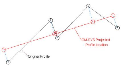
Note that XYZGMS converts a multi-segment line into a single-segment profile as shown below. The black line represents the original profile as digitised by the user. The red line is the location of the model profile in real-world X,Y space with values projected perpendicularly onto the model profile. The model-profile azimuth is based on the first and last points in the original profile. The profile location is then shifted to minimize the average mis-fit.
If you prefer to use distance along the line as the GM-SYS Profile Modelling X-coordinate, use the DISTCHAN GX (Utility | Make distance channel..) to generate a "X_dist" channel. Create a "Y_dist" channel containing all 0's. Then run the XYCOPY GX (Coordinates | Changes coordinates..) to set the default X,Y to X_dist,Y_dist. After running GMSMARK, you can easily resort the original X,Y by running the XYGET GX (Coordinates | Restore backup XY).
Got a question? Visit the Seequent forums or Seequent support
© 2023 Seequent, The Bentley Subsurface Company
Privacy | Terms of Use