
Section Layout Editor
The section layout editor is used to create and modify section layouts. The same layout editor is also used to create layout templates that can be applied to sets of sections to simplify the process of creating similar section layouts.
To learn more about layout templates which use the same layout editor as described in this topic, see also Layout Templates.
This topic focuses on the construction of the section layout using the layout editor. It is divided into:
- Working With Section Layouts and Layout Templates
- Creating New Section Layouts
- How the Section Layout Editor is Arranged
- General Concepts Used in Editor
- Bulk Editing Multiple Objects
- Displaying Section Layouts in the Scene
- Copying Section Layouts
- Exporting Section Layouts
These topics address composing and styling the elements that appear on the layout:
- Projection Algorithm
- Setting Page Properties
- Setting the Section Extents and Position
- Adding and Styling Models
- Adding and Styling Drillholes and Planned Drillholes
- Adding and Styling Surfaces
- Adding and Styling Lines
- Adding and Styling Points
- Markers
- Adding and Styling Structural Data
- Setting Up the Legend Group
- Plan Views
- Strip Views
- Adding a Title Block
- Adding and Organising Comments
Working With Section Layouts and Layout Templates
A section (1) is presented on a section layout (2) that arranges the section alongside other information such as the section title, legend and location reference. To make multiple section layouts consistent and to reduce the work involved in creating them, a layout template (3) can be created to define the overall layout structure that will be replicated on each section layout.
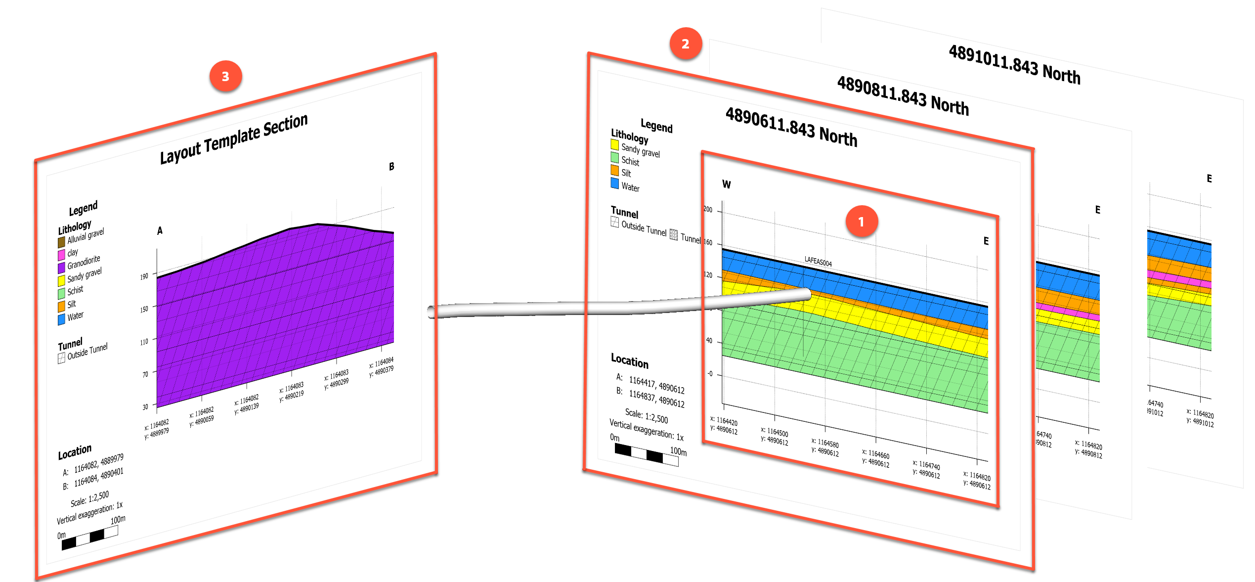
When creating a single, stand-alone section, it is not necessary to utilise a layout template. In other cases where multiple sections are being defined, it is usually desirable to:
- Start by creating a layout template. See Creating a New Layout Template for details.
- Create your section definitions using one of:
- Copy the layout template design to the sections to create a section layout for each section. See Applying Layout Templates to Sections
Any changes to the layout template will propagate to the child section layouts it was copied to. It is also possible to modify the child section layouts individually, but changing a child section layout breaks the relationship with the layout template, it does not affect the layout template, and future changes to the layout template will not change the modified child section layout.
You can create any number of layout templates, which is useful to manage section layouts that need different overall structures, such as wide panoramas versus tall slim slices.
Creating New Section Layouts
This describes how to set up a new layout for sections other than plan sections. See Creating Plan View Layouts for Plan Views for information on setting up layouts for plan sections.
When a number of similar section layouts are needed, it is not necessary to create them individually in this manner. The alternative method is to create a layout template and copy that template to the sections. This will automatically create the section layouts for each section the template is applied to. See Layout Templates for more information.
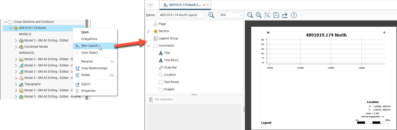
To create a section layout, right-click on the section in the project tree and select New Layout. A new tab will appear in which you will be able to make changes to the section layout. This tab has a layout tree that you can use to change different parts of the section and add data to it. See How the Section Layout Editor is Arranged to familiarise yourself with the editor.
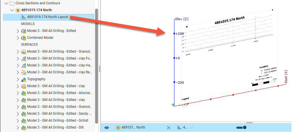
In the project tree, the section layout is saved as part of the section. Drag the layout into the scene to display it:
Edit the section layout by double-clicking on it in the project tree.
How the Section Layout Editor is Arranged
The section layout editor is used for both section layouts and layout templates. To open the section layout editor, double-click on a section layout or a layout template in the project tree.
The section layout editor consists of two main parts:
- The layout tree panel with the properties panel below it
- The preview of the layout
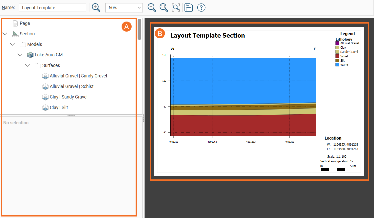
The toolbar has zoom controls for the preview that allow you to choose a specific zoom percentage from a list of options, along with Zoom in( ), Zoom out(
 ), Actual size(
 ) and Fit window(
 ) buttons. There are also Save (
 ) and Export (
 ) buttons.
Long section layouts get an additional Projection algorithm option.

The appearance of all objects can be customised without changing how objects from the project tree are displayed in the scene. You can customise the section layout by:
- Adding models, surfaces, lines, points and structural data
- Adding drillholes and planned drillholes
- Changing the page size, orientation and margins
- Adding a title and title bar, a scale bar, legends, annotations and images, such as a standard form or logo
In the section editor, the layout tree shows the different layers that can be added to the page. The different parts of the layout tree as they relate to the page preview are shown below:
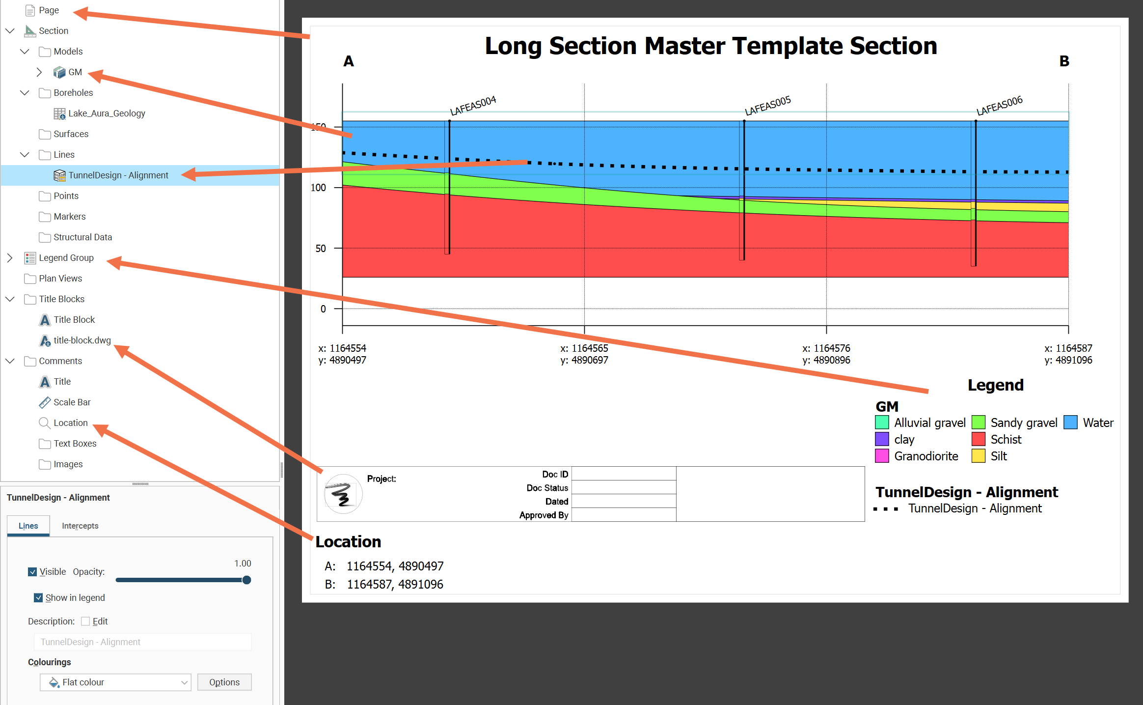
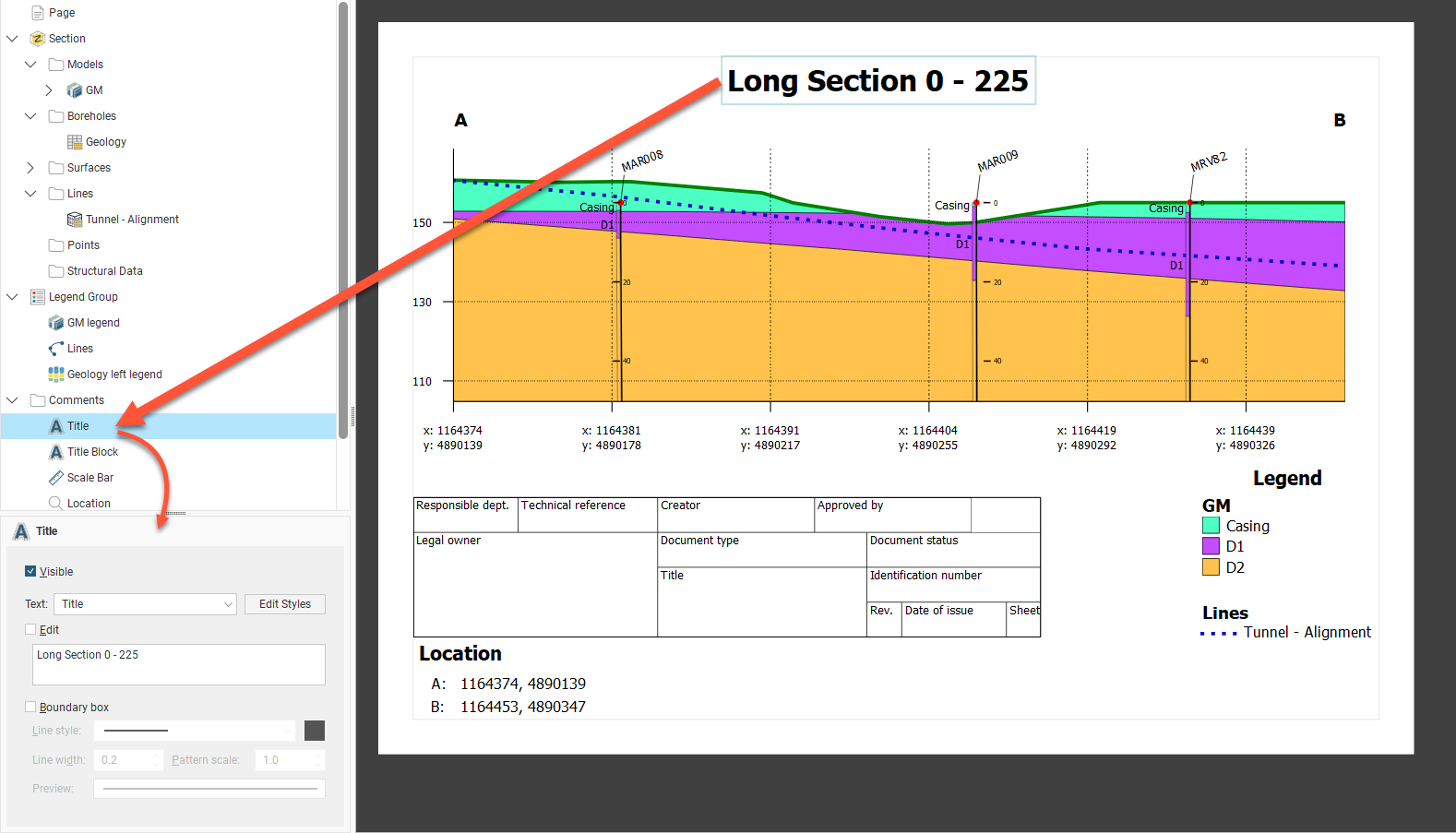
When you select an object in the layout tree, it will be highlighted by a blue line on the page. In the example above, the Lines object Tunnel - Alignment is selected. Click on an object in the page preview to move or resize it. This will also select the object in the layout tree and you can see what properties can be changed. For example, in the preview, click on the Title to view its styling options:
General Concepts Used in Editor
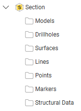
The folders below the Section object are used to add and organise models, drillholes, surfaces, lines, points and structural data on the section and to customise how they are displayed:
You can add new objects by right-clicking on a folder and selecting an Add option:
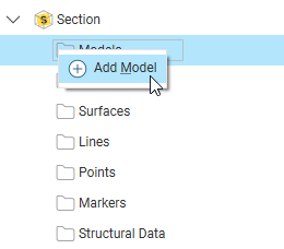
- For the Add Model and Add Surface options, you will be able to choose from the models available in the project.
- For the Drillholes folder, there are two options, Add Drillholes and Add Planned Drillholes. For both options, you can choose from the drillholes and planned drillholes available in the project.
- For the lines, points and structural data, the Add options let you choose from lines, points, and structural data available in the project.
It is not necessary to evaluate objects in the project on the section before working in the section layout editor. When you add an object to the layout, Leapfrog Geo will automatically evaluate it on the section.
Models, drillholes, surfaces, lines, points and structural data occupy the same space on the section layout, and opacity settings and an object’s position among the layers can be changed to emphasise relevant information. To change the order of objects on the page, right-click on them and select an option:
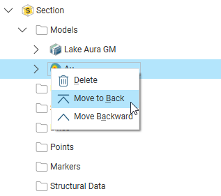
Models will always be among the lower layers, with lines on top of all the other layers. You can remove objects from the layout by right-clicking on them and selecting Delete.
Most objects added to a section layout have a Visible checkbox for each component part that it is possible to display:
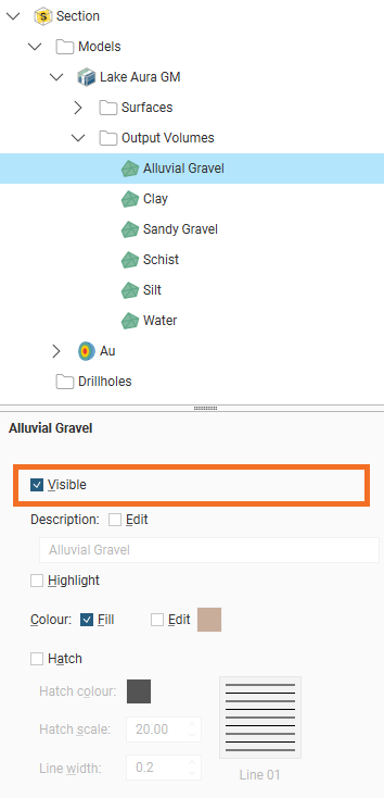
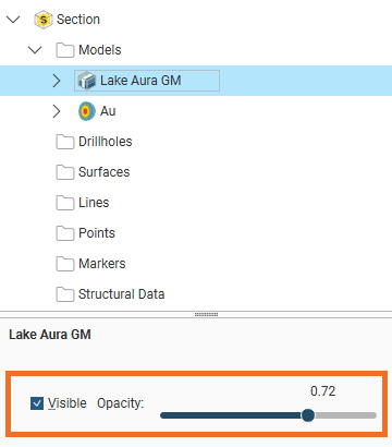
Some also have Opacity controls for allowing some background objects to be seen through the semi-transparent object.
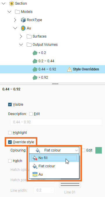
Numeric models control visibility of output volumes in a different way. Instead of a Visible checkbox, first check the Override style checkbox, then from the Colouring dropdown, select No Fill:
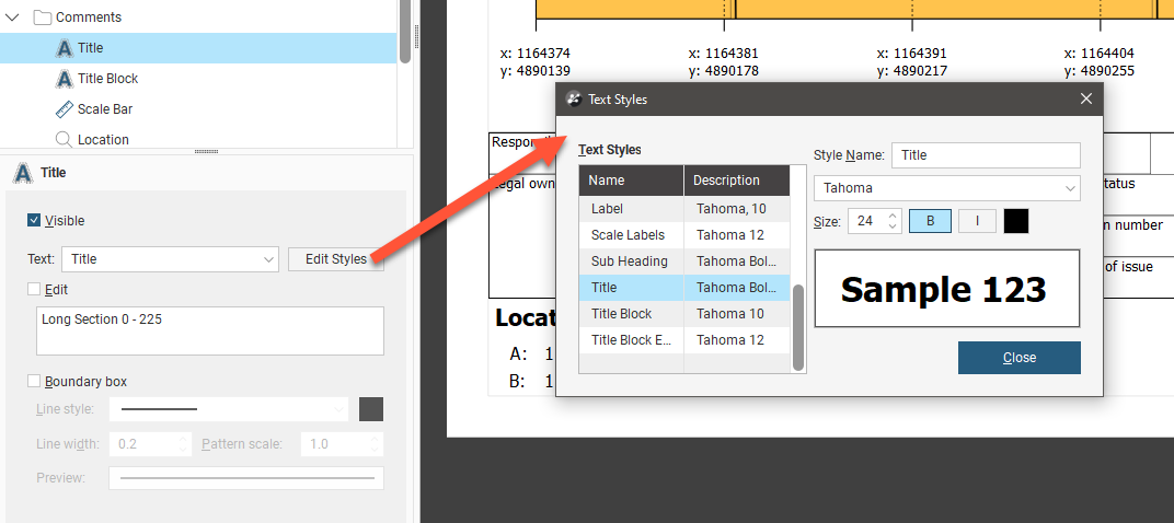
Text displayed in the section layout is controlled by a style sheet that can be accessed whenever you are editing a text object. For example, clicking on Edit Styles for the Title opens the list of Text Styles with the Title selected, but also allows you to change the appearance of styles used for other text objects visible in the preview:
Bulk Editing Multiple Objects
You probably want similar objects evaluated onto your section layout to be represented in the same way, but when they appear as multiple objects in the section editor that could involve multiple repetitive changes. To avoid this, multiple selection is supported allowing the bulk editing of objects. For instance, you could select multiple drillhole objects and edit the collar symbol and labels in one step, making them all match.
Commonly shared fields will appear in the properties panel below the tree view; changes made to these fields will be applied to all the selected objects.
Objects that can be selected for bulk edits include:
- Models
- Drillholes
- Surfaces
- Points
- Structural Data
- Comments
- Legends
Objects that cannot be selected for bulk editing are:
- Lines
- Objects that have multiple visibility toggles
When objects are selected that have formatting options that differ, the properties panel will show an indicator to warn that any changes to a field will unify currently different choices:
- The word ‘mixed’ will appear in text and value fields, and instead of a value adjacent to controls such as sliders
- Two triangle colours will split a colour chip if there are two or more colours selected
- A dash will appear in the place of a tick for checkbox fields.
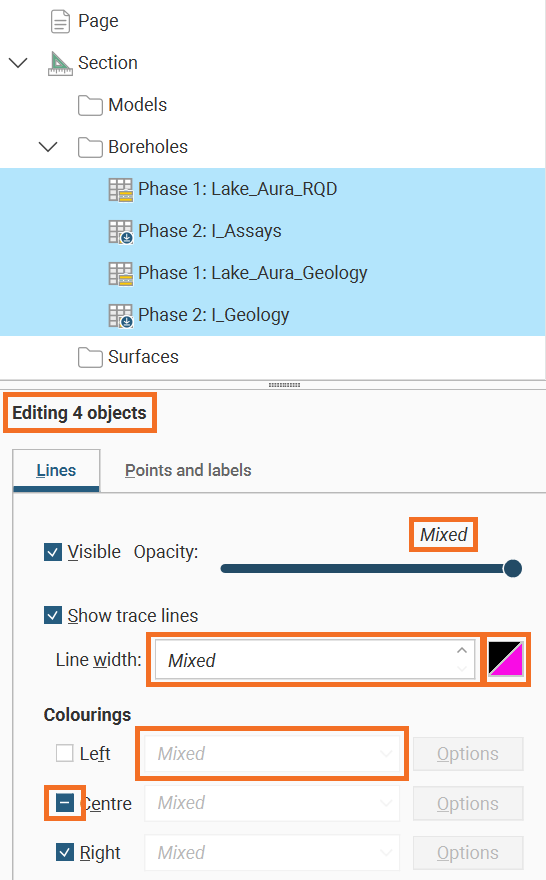
In most instances, common formatting options that will appear below the tree view will include visibility and opacity controls, with some object selections also allowing you to toggle labels.
Displaying Section Layouts in the Scene
Sections can be displayed in the scene by dragging a layout into the scene to see the section in relation to models in the scene, but the usual way sections will be viewed is by exporting them as files to be imported into other software or as documents to be printed.
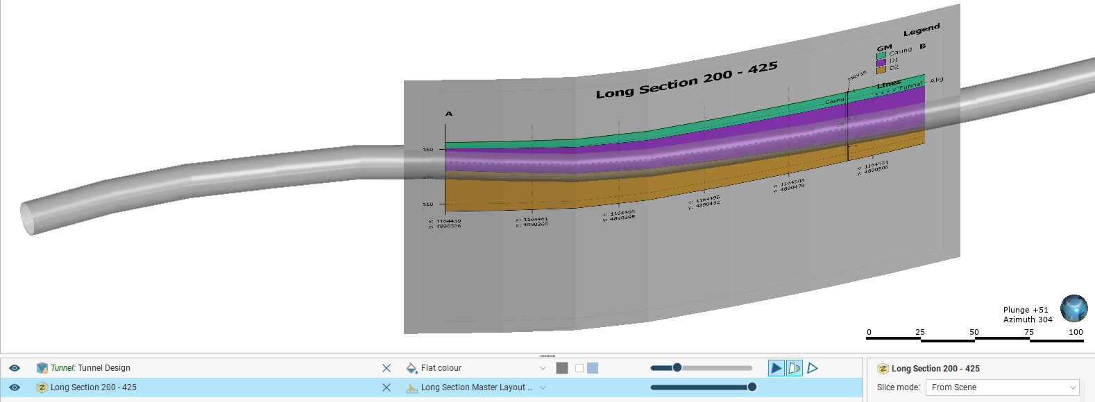
Some sections will be too large to display in the scene, which will be indicated in the section layout editor.
Copying Section Layouts
If you have already created a section layout and wish to reuse it, you can copy it to other sections.
When you have a number of similar sections in a project, instead of creating one section layout and copying it to other sections, use a layout template. Using a layout template maintains a reference from the parent template to the child layouts and they can all be updated by modifying the template layout. This does not happen when a section layout is copied to another section. See Layout Templates for more detail on how to create layout templates and apply them to sections.
To copy a layout, right-click on the layout you wish to copy and select Copy Layout To. In the window that appears, a summary of the information that will be copied is displayed so you can see what information will be copied to the selected sections. Move the sections you wish to copy the layout to into the Selected Sections list, then click OK.
Search for items in a list by pressing Ctrl-F. A Find window will appear that you can use to search the list. You can choose whether or not to match case in the search and whether or not to match the whole label. You can search forwards or backwards and you can select all list items that match the current search.
A copy of the layout will appear in the project tree under each section you selected.
Copying a section layout copies the evaluations used in the original section layout, together with the page size and orientation and the position of the layout tree objects on the page. How models, surfaces and drillholes are copied depends on the section to which the layout is being copied:
- All models, surfaces, lines, points and structural data objects that can be displayed on the section will be copied.
- The drillholes copied to the layout will depend on the type of section the layout is being copied from and whether or not a filter is set for the layout:
- If no distance filter was set for the original layout, all drillholes selected for the original layout will be copied.
- If a distance filter was applied to the original section, the filter will be applied and drillholes selected that are within that distance of the section to which the layout is being copied.
- When a layout is being copied to a long section, drillhole evaluations will not be copied with the section layout unless the original layout is also from a long section.
Exporting Section Layouts
Once you have finished adjusting the section layout, you can export it in one of the following formats:
- PDF Files (*.pdf)
- Scalable Vector Graphics Files (*.svg)
- PNG Image Files (*.png)
- GeoTIFF Files (*.tiff, *.tif)
GeoTIFF files are not an export option for long sections unless using batch export.
Click the Save and Export button () at the top of the window or right-click the layout in the project tree and select Export Layout from the pop-up menu. You will be prompted for a filename and location.
You can also batch export multiple section layouts. To do this, right-click on the Sections, Plans and Contours folder and select Batch Export Layouts. All selected sections can be exported as a single PDF or individually in PDF file (*.pdf), Scalable Vector Graphics file (*.svg), PNG image (*.png) or GeoTIFF (*.tiff, *.tif) formats. When section layouts are exported individually, all outputs can be combined into a zip archive.
In the window that appears, select the layouts you wish to export, then select a format. If you select a format other than Single PDF, you can combine all outputs into a zip archive. Select where you wish to save the outputs, then click Export.
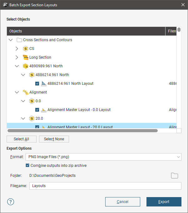
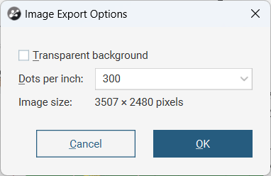
If the export format is selected as a GeoTIFF file, an Image Export Options window will appear where the resolution can be specified in Dots per inch and you can specify whether or not the image will have a Transparent background.
The export will be processed as a background task that appears in the processing list.