Editing Faults
Once a fault has been defined, you can refine it in several ways:
- Add other data. This option is available for faults created as surfaces, but not for those created as vertical walls. Right-click on the surface to see the options available, which will depend on how the surface was created.
- Edit the surface with a polyline. Right-click on the surface in the project tree and select either Edit > With Polyline. See Editing Surfaces With Polylines for more information.
- Edit the surface using structural data. Right-click on the surface and select Edit > With Structural Data. See Editing Surfaces With Structural Data for more information.
The rest of this topic describes other options for editing faults. It is divided into:
Surfacing Options for Faults
To change surfacing options for a fault, double-click on the fault in the project tree, then click on the Surfacing tab.
See Surface Resolution for a Geological Model and Honouring Surface Contacts for information about the settings in the Surfacing tab.
The settings in the Surfacing tab will be disabled if the fault inputs have been replaced with a mesh.
Boundary Filtering
When data objects are added to a fault, there are two ways to handle the data that lies outside the fault boundary:
- Filter the data. The fault is only influenced by the data that falls inside the fault boundary.
- Leave the data unfiltered. The fault is influenced by the data both inside and outside the fault boundary.
The Boundary filter setting determines how data used to define the fault is filtered:
- Off. Data is not filtered.
- All data. All data is filtered.
- Drilling only. Only drillhole data and data objects derived from drillhole data are filtered.
- Custom. Only the data objects specified in the Inputs tab are filtered.
Snapping to Data
There is a Snap to data setting for a geological model as a whole that is set in the Geological Model > General tab (see Editing a Geological Model). Snap to data can also be set on a surface-by-surface basis by double-clicking on the surface in the project tree and then clicking on the Surfacing tab.
For faults, the options are:
- Inherit from GM. The setting for the geological model as a whole is used. This is the default setting.
- Off. The fault surface does not snap to the data used to create it.
- All data. The fault surface snaps to all data within the Maximum snap distance, which includes drillhole data and any data added to the fault.
- Drilling only. The fault surface snaps to drillhole data and data objects derived from drillhole data within the Maximum snap distance but not to other data used to modify the fault. For example, the fault surface will honour points data derived from drillhole data, but not points data imported into the Points folder.
- Custom. The fault surface snaps to the data objects indicated in the Inputs tab.
Take care in enabling snapping and in selecting what data the surface will snap to, as the more data you include, e.g. by setting a large Maximum snap distance or selecting All data for Snap to data, the greater the possibility that errors in the data or assumptions inherent in interpretations (e.g. polylines) will cause distortions in the meshes. If you do enable snapping, it is best to snap only to drilling data. See Honouring Surface Contacts for more information on these settings.
If you need the fault surface to honour drillhole data but treat other data objects as interpretations, select Drilling only. To honour some data objects while treating others as interpretations, select Custom, then click on the Inputs tab to enable snapping for individual objects.
Changing Fault Inputs
For faults, the Inputs tab shows all the data objects used to create the fault and whether the Snap and Boundary filter options are enabled for each object used to define the fault. If an input has any query filters defined, you can select one in this window.
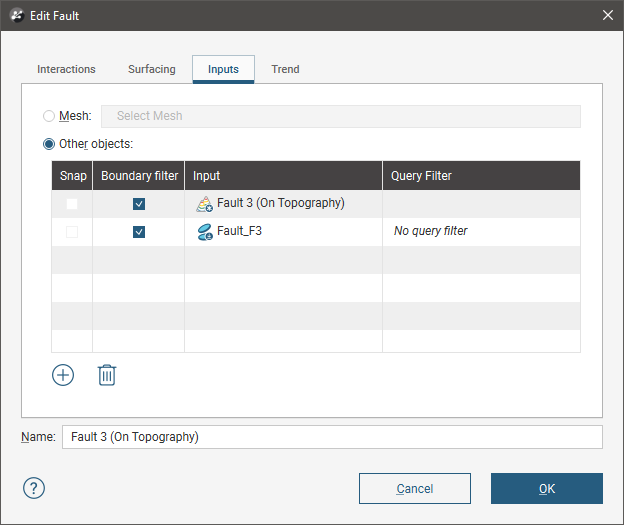
You can also replace the fault’s inputs with a single mesh or add more data to the fault.
Replacing Fault Inputs With a Single Mesh
To replace the fault inputs with a single mesh, click on the Mesh option, then select from the meshes available in the project.
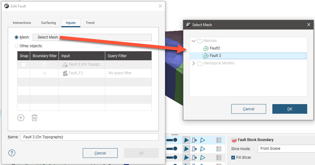
When you select a single mesh to define the fault, all other inputs listed in the Inputs tab will be removed from the fault. This can result in objects being deleted from the project. For example, if the fault has been edited using a polyline, the polyline will be deleted when the inputs are replaced with the mesh. If you wish to retain such inputs, be sure to share the object before changing the inputs. See Sharing Objects for more information.
The snap and boundary filtering controls in the Surfacing tab will be disabled as the settings from the geological model will be used. The settings in the Trend tab will also be disabled as it is not possible to set a trend for a fault defined from a mesh.
Adding Data to the Fault
To add more data to the fault, click on the Select Objects button, then select from the suitable objects available in the project.
Snap Settings for Individual Inputs
The Snap setting determines whether or not the faults surface honours a particular data object. Often, surfaces should honour drillhole data and treat data objects such as polylines and GIS data as interpretations, as discussed in Honouring Surface Contacts. To change snap settings for a fault, click on the Surfacing tab and set Snap to data to Custom. You will then be able to change Snap settings in the Inputs tab.
Boundary Filtering Settings for Individual Inputs
When data objects are added to a fault, there are two ways to handle the data that lies outside the fault boundary:
- Filter the data. The fault is only influenced by the data that falls inside the fault boundary.
- Leave the data unfiltered. The fault is influenced by the data both inside and outside the fault boundary.
To change the Boundary filter settings for each object used to define a fault, click on the Surfacing tab and set Boundary filter to Custom. You will then be able to change Boundary filter settings in the Inputs tab.
Applying a Trend to a Fault
To apply a trend to a fault, either:
- Double-click on the fault in the project tree, then click on the Trend tab.
- Right-click on the fault in the project tree and select Adjust Surface. This opens the Edit Fault window with the Trend tab displayed.
See Global Trends for information on using the controls in this tab.
The settings in the Trend tab will be disabled if the fault inputs have been replaced with a mesh.
Got a question? Visit the Seequent forums or Seequent support