Structural Surfaces
A structural surface uses contact data and non-contact structural data to create a surface. A structural surface can interact with other volumes in the model as a deposit, an erosion or an intrusion contact surface. The shape of the structural surface is suggested by the non-contact structural data used.
When creating a structural surface, there are two options for declustering the non-contact structural data:
- The input data is automatically declustered as part of creating the structural surface. There are no additional controls that determine how the data is declustered.
- Use a declustered structural data set as the non-contact input to the surface. This approach is recommended over the first approach as you can change how the data is declustered.
The rest of this topic describes how to create and work with a structural surface. It is divided into:
- Creating a Structural Surface
- The Structural Surface in the Project Tree
- Refining a Structural Surface
- Surfacing Options for a Structural Surface
- Non-Contact Structural Inputs Settings
- Applying a Trend to a Structural Surface
- Value Clipping
Creating a Structural Surface
To create a new structural surface, right-click on the Surface Chronology and select New Structural Surface. The New Structural Surface window will appear:
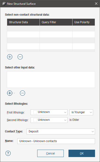
Use the Add buttons to add non-contact structural data and on-surface contacts, then set the First lithology and Second lithology. Other settings are:
- Query Filter. Select from the query filters defined for the selected structural data object.
- Use Polarity. Untick the box to use tangents only.
- Contact Type. Structural surfaces can be deposit, erosion or intrusion contacts. The same algorithm is used for each setting; the only difference is in how the surface interacts with other surfaces.
The Structural Surface in the Project Tree
The name Leapfrog Geo automatically assigns to a structural surface is the lithologies assigned to each side of the surface. In the project tree, expand the surface to see how it was made:
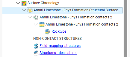
As further refinements are made to the surface, that information will also be added to the project tree. See Refining a Structural Surface below for more information.
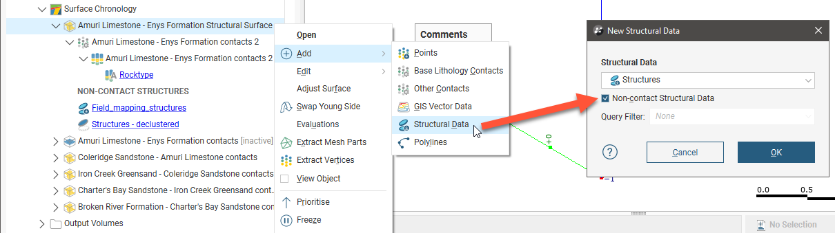
To add more non-contact structural data to the surface, right-click on it in the project tree and select Add > Structural Data. In the window that appears, tick the box for Non-contact Structural Data:
Refining a Structural Surface
You can refine structural surfaces in several ways:
- Add other data. Right-click on the surface to see the options available, which will depend on how the surface was created. See Adding Data to Surfaces for more information.
- Edit the surface with a polyline. Right-click on the surface in the project tree and select either Edit > With Polyline. See Editing Surfaces With Polylines for more information.
- Edit the surface using structural data. Right-click on the surface and select Edit > With Structural Data. See Editing Surfaces With Structural Data for more information.
To edit the surface’s settings, double-click on it in the project tree. In the Lithologies tab, change the lithologies assigned to each side of the surface, if required.
You can swap the younging direction if the direction was assigned incorrectly when the surface was created. The change will be reflected in the scene. Note that changing the younging direction does not change which lithology is older or younger.
The Contact Type setting determines how the structural surface interacts with other lithologies, as described in Contact Surfaces. A structural surface can be a deposit, erosion or intrusion contact surface.
For information on other techniques for refining structural surfaces, see Surfacing Options for a Structural Surface below.
Surfacing Options for a Structural Surface
Surfacing options for a structural surface are accessed by double-clicking on the surface in the project tree and clicking on the Surfacing tab. There are additional settings related to boundary filtering and snapping to data in the Inputs tab.
Setting the Surface Resolution
See Surface Resolution for a Geological Model for information about the surface resolution settings in the Surfacing tab.
Boundary Filtering
When data objects are added to a surface, there are two ways to handle the data that lies outside the surface’s boundary:
- Filter the data. The surface is only influenced by the data that falls inside the surface’s boundary.
- Leave the data unfiltered. The surface is influenced by the data both inside and outside the surface’s boundary.
The boundary of a structural surface can be the geological model boundary or a fault block boundary.
The Boundary filter setting determines how data used to define the surface is filtered:
- Off. Data is not filtered.
- All data. All data is filtered.
- Drilling only. Only drillhole data and data objects derived from drillhole data are filtered.
- Custom. Only the data objects specified in the Inputs tab are filtered.
Snapping to Input Data
Often, surfaces should honour drillhole data and treat data objects such as polylines and GIS data as interpretations. See Honouring Surface Contacts.
There is a Snap to data setting for a geological model as a whole that is set in the Geological Model > General tab (see Editing a Geological Model). Snap to data can also be set on a surface-by-surface basis by double-clicking on the surface in the project tree and then clicking on the Surfacing tab.
For individual contact surfaces, the options are:
- Inherit from GM. The setting for the geological model as a whole is used. This is the default setting.
- Off. Surfaces do not snap to the data used to create them.
- All data. Surfaces snap to all data within the Maximum snap distance, which includes drillhole data and any data added to the surfaces.
- Drilling only. Surfaces snap to drillhole data and data objects derived from drillhole data within the Maximum snap distance but not to other data used to modify the surfaces.
- Custom. Surfaces snap to the data objects indicated in the Inputs tab for each surface.
Take care in enabling snapping and in selecting what data the surface will snap to, as the more data you include, e.g. by setting a large Maximum snap distance or selecting All data for Snap to data, the greater the possibility that errors in the data or assumptions inherent in interpretations (e.g. polylines) will cause distortions in the meshes. If you do enable snapping, it is best to snap only to drilling data. See Honouring Surface Contacts for more information on these settings.
If you need a surface to honour drillhole data but treat other data objects as interpretations, select Drilling only. To honour some data objects while treating others as interpretations, select Custom, then click on the Inputs tab to enable snapping for individual objects.
Non-Contact Structural Inputs Settings
For the non-contact structural inputs, you can:
- Change the Query Filter setting. Select from the query filters defined for the selected structural data object.
- Change the Use Polarity setting. Untick the box to use tangents only.
- Change the Boundary filter setting, if the Boundary filter setting in the Surfacing tab is set to Custom.
Applying a Trend to a Structural Surface
There are two ways to change the trend for a structural surface:
- Right-click on the surface in the project tree and select Adjust Surface.
- Double-click on the surface in the project tree and then click on the Trend tab.
See Global Trends for more information.
Value Clipping
In the Value Clipping tab, you can manipulate the data distribution by clipping the data. Clipping caps values that are outside the range set by the Lower bound and Upper bound values. For example, if you change the Upper bound from 16.00 to 10.00, distance values above 10.00 will be regarded as 10.00.
When Automatic clipping and Do clipping are enabled, Leapfrog Geo sets the Lower bound and Upper bound from the data. To change the Lower bound and Upper bound, untick Automatic clipping, tick Do clipping and then change the values.
Got a question? Visit the Seequent forums or Seequent support