
Butterworth (BTWR)
Use the Butterworth option to apply a butterworth filter.
Butterworth Filter dialog options
|
Cutoff wavelength |
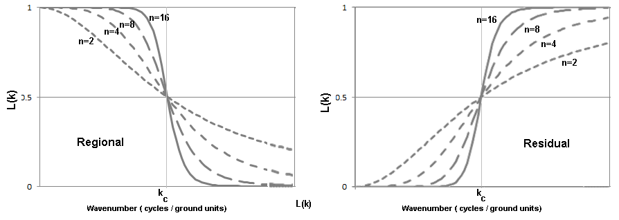
The cutoff wavelength in ground units. See illustration, this parameter is equivalent to kc-1. This wavelength is converted to wavenumber for the actual filter calculation. |
|
Filter order |
Integer power of the Butterworth filter, controlling the degree of the sharpness of the cutoff. A lower power will result in a smoother filter cutoff. By default a power of 8 is used. |
|
Low pass High pass |
Specify the range of frequencies in your data that you would like to preserve. Selecting Low pass will preserve frequencies lower than the supplied cutoff wavelength. Selecting High pass will preserve frequencies higher than the supplied cutoff wavelength. Low pass is selected by default. |
Application Notes
Low pass Butterworth filter

High pass Butterworth filter

Where:
|
kc |
Inflection point of wavenumber cutoff in cycles/ ground unit. |
|
n |
Positive integer value determining the degree of sharpness of the cutoff. |
The Butterworth filter is excellent for applying straightforward high-pass and low-pass filters, in particular because if allows you to control the sharpness of the filter around the wavelength cutoff. Many other low and high pass filters result in “ringing” (Gibbs phenomenon) in the output, because they have a sharp “cut-off” either side of the cutoff wavelength. Ringing generally manifests as “waves” emanating from the edges of high amplitude anomalies (see below).
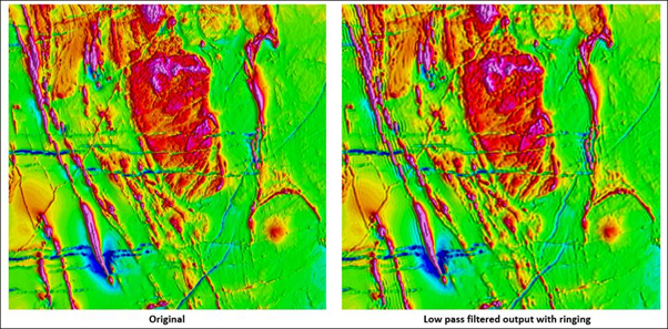
Original magnetic data (left), low pass filtered magnetic data with ringing (right)
The “Filter order” parameter controls the degree of filter roll-off, centered on the cutoff wavenumber, which enables the user to eliminate ringing from the result. If ringing is observed in the filtered result, reduce the filter order by one and re-apply the filter.
A common, but more complicated alternative is the Cosine filter (COSN).
Got a question? Visit the Seequent forums or Seequent support
© 2023 Seequent, The Bentley Subsurface Company
Privacy | Terms of Use