
Butterworth Bandpass (BTWRB)
Use the Butterworth Bandpass option to apply a Butterworth bandpass filter.
Butterworth Bandpass Filter dialog options
|
Long wavelength cutoff |
Long-wavelength central cutoff, in ground units. |
|
Short wavelength cutoff |
Short-wavelength central cutoff, in ground units. |
|
Filter order |
Controls the sharpness of the filter at the cutoff wavelengths. The default is 8. |
Application Notes
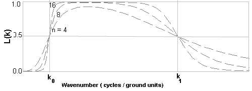
The Butterworth bandpass filter passes the desired mid-wavenumber range while attenuating the low and high extremes of the wavenumber spectrum. The Filter order controls the degree of the sharpness of the cutoff wavenumbers:
-
Higher values make the filter shape closer to an ideal bandpass operator.
-
However, an ideal bandpass filter is not recommended because it produces ringing artifacts (Gibbs’ Phenomenon).
A common—but more complex—alternative is the Cosine Bandpass roll-off filter (FFTCOSNB).
Butterworth Bandpass Filter
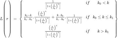
Where:
|
k0 |
Low wavenumber cutoff (cycles per ground unit). |
|
k1 |
High wavenumber cutoff (cycles per ground unit). |
|
n |
Positive integer determining the sharpness of the cutoff. |
Wavenumber Domain Variable Definitions
|
The following variables are used in the wavenumber domain: |
||
|
k |
Wavenumber increment, used to depict a radially symmetrical variable. |
Where: np: number of points cs: cell size |
|
μ |
X-component of the wavenumber. |
|
|
v |
Y-component of the wavenumber. |
|
|
r |
Radial component of the wavenumber. |
|
|
θ |
Angular (polar) component of the wavenumber. |
|


Ground unit refers to the survey ground units defined in your grid (e.g., metres or feet). Ground units may be left undefined.
Got a question? Visit the Seequent forums or Seequent support
Copyright (c) 2026 Bentley Systems, Incorporated. All rights reserved.
Privacy | Terms of Use