
Notch (NOTCH)
Use the Notch option to apply a notch filter to your data.
Notch Filter dialog options
|
Central wavelength |
The central wavelength to be rejected, in ground units. |
|
Power factor |
Controls the width of the rejected band. A larger value produces a wider rejection band. (Default=1). |
|
Depth factor |
Controls how sharply the transition occurs between the rejected band and the passed bands. A smaller value results in a more abrupt rejection. (Default = 2). |
Application Notes
A notch filter is used to reject a selected mid‑wavenumber range while preserving both the low‑ and high‑frequency components of the spectrum. The power factor determines the width of the rejection band, while the depth factor controls the sharpness of the filter’s transition (i.e., how steeply energy is attenuated around the central wavelength).
This filter is useful when suppressing a specific band of wavelengths, such as periodic noise, without altering the lower or higher parts of the spectrum.
Notch Filter Operator
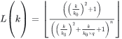
Where:
|
k0 |
Cutoff (central) wavenumber in cycles per ground unit |
|
n |
Power of the filter function (controls width) |
|
q |
Degree of the filter function (controls depth/abruptness) |
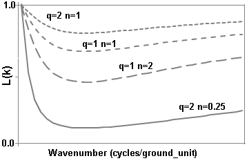
Wavenumber Domain Variable Definitions
|
The following variables are used in the wavenumber domain: |
||
|
k |
Wavenumber increment, used to depict a radially symmetrical variable. |
Where: np: number of points cs: cell size |
|
μ |
X-component of the wavenumber. |
|
|
v |
Y-component of the wavenumber. |
|
|
r |
Radial component of the wavenumber. |
|
|
θ |
Angular (polar) component of the wavenumber. |
|


Ground unit refers to the survey ground units defined in your grid (e.g., metres or feet). Ground units may be left undefined.
Got a question? Visit the Seequent forums or Seequent support
Copyright (c) 2026 Bentley Systems, Incorporated. All rights reserved.
Privacy | Terms of Use