Serial Sections
This topic describes the process of creating a serial section, which is a series of cross sections taken at an offset from a single base section.
The type of section that allows for a series of sections following along a single line is called a long section, and is described in Long Sections.
This topic is divided into:
- Setting the Base Section
- Setting the Offset Sections
- The Serial Section in the Project Tree
- Displaying a Serial Section
- Exporting a Serial Section
To create a serial section, add a model to the scene. Next, right-click on the Cross Sections and Contours folder and select New Serial Section. The New Serial Section window will appear and planes representing the base section and the offset sections will be added to the scene:
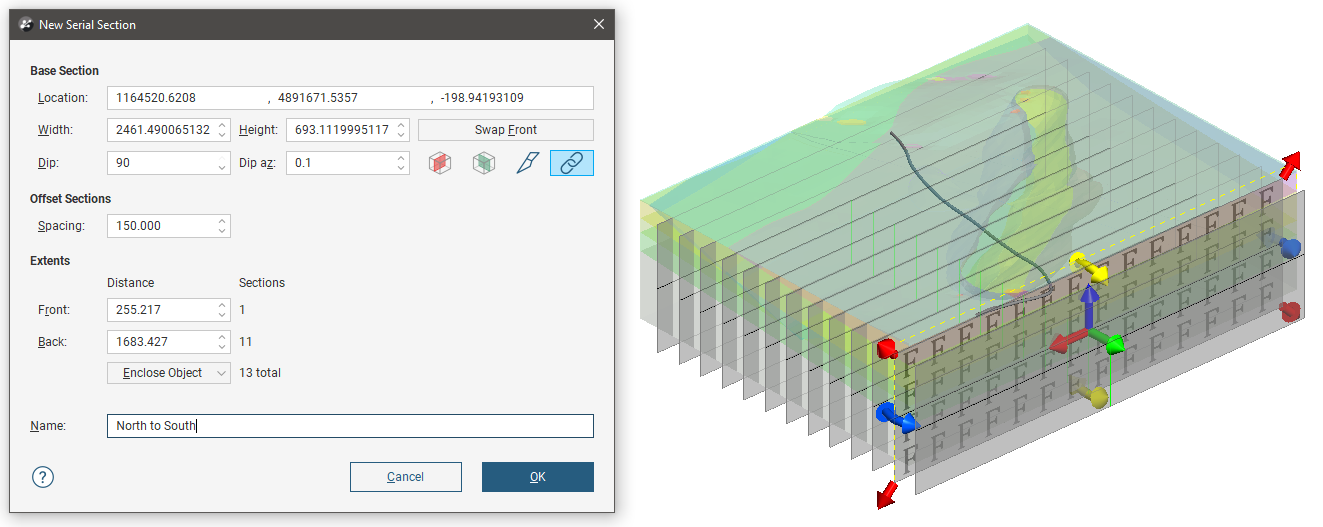
If the slicer is already in the scene when you select New Serial Section, the position of the slicer will be used to define the initial orientation of the base section.
Setting the Base Section
The handles in the scene control the position of the base section and work in the same manner as the moving plane controls (see The Moving Plane).
The front (F) and back (B) of the base section plane are indicated in the scene. To swap the front and back, click the Swap Front button.
Two buttons in the New Serial Section window let you create a base section that is aligned north-to-south (![]() ) or east-to-west (
) or east-to-west (![]() ). The other two buttons are active when the slicer is in the scene. Clicking the Set section to slicer button (
). The other two buttons are active when the slicer is in the scene. Clicking the Set section to slicer button (![]() ) creates a cross section from the position of the slicer in the scene. When the Lock section to slicer button (
) creates a cross section from the position of the slicer in the scene. When the Lock section to slicer button (![]() ) is enabled it will be highlighted in blue, and moving the position of the slicer will update the position of the cross section in the New Serial Section window, and moving the orientation of the base section will change the position of the slicer.
) is enabled it will be highlighted in blue, and moving the position of the slicer will update the position of the cross section in the New Serial Section window, and moving the orientation of the base section will change the position of the slicer.
Setting the Offset Sections
The number of offset sections is determined by the value of the Spacing setting and the Front and Back Extents:
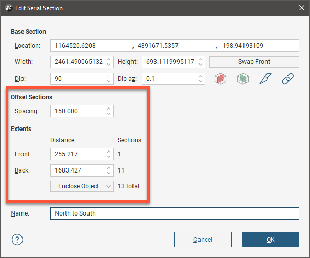
You can change the number of offset sections by:
- Changing the Spacing setting, which changes how far apart each of the section slices are. The number of offset sections will be recalculated and updated in the scene.
- Changing the Front or Back settings. For example, increasing the Front setting adds an offset section on the front of the base section, increasing the extents by the value of Spacing.
- Changing the object used to define the extents. Select an object from the Enclose Object list. The base section will be moved to the centre of the selected object.
Click OK to create the section.
The Serial Section in the Project Tree
In the project tree, the serial section includes the individual cross sections:
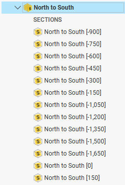
At this point no sub section in the serial section has any defined layout.
First, select the objects you wish to evaluate onto the serial section by right-clicking the parent serial section object in the project tree and selecting Evaluations from the popup menu. Add the objects you want to evaluate onto the section to the Selected objects list.
Next, right-click each serial section , selecting New Section Layout from the popup menu. Design the section layout using the section editor. For more information on editing sections, see Section Layouts.
Serial sections do not use a master section layout. However, having created one section layout for a serial section, you can copy the layout to all the other sections. In the project tree, right-click the new section layout and select Copy Layout To from the popup menu. Select the other serial sections in the Available Sections list and move them to the Selected Sections list using the right arrow button.
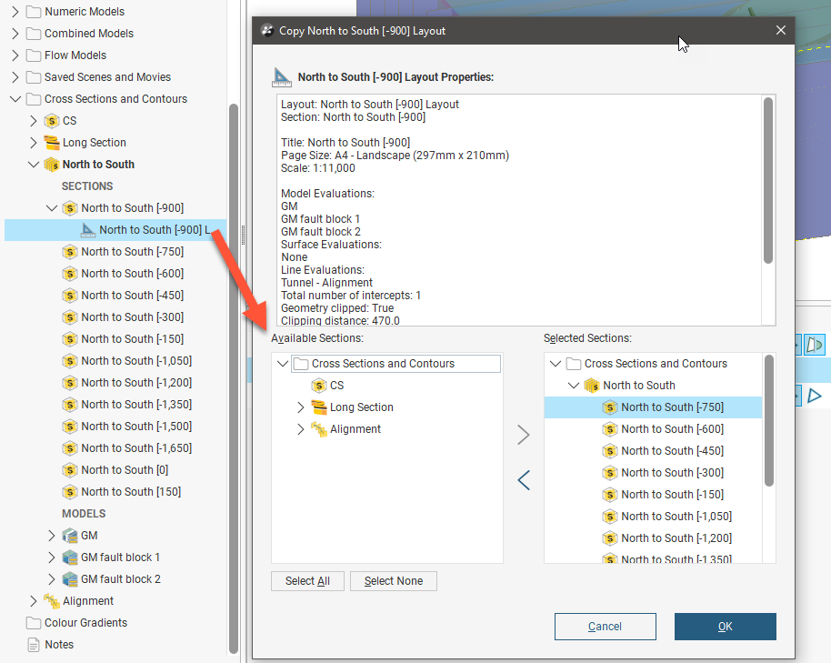
Each layout can then be further customised as required.
Displaying a Serial Section
When you display a serial section in the scene, you can add the slicer to the scene and use it to move easily between the sections in the stack. To do this, click on the slicer in the shape list, then select the base section from the Set location to list:
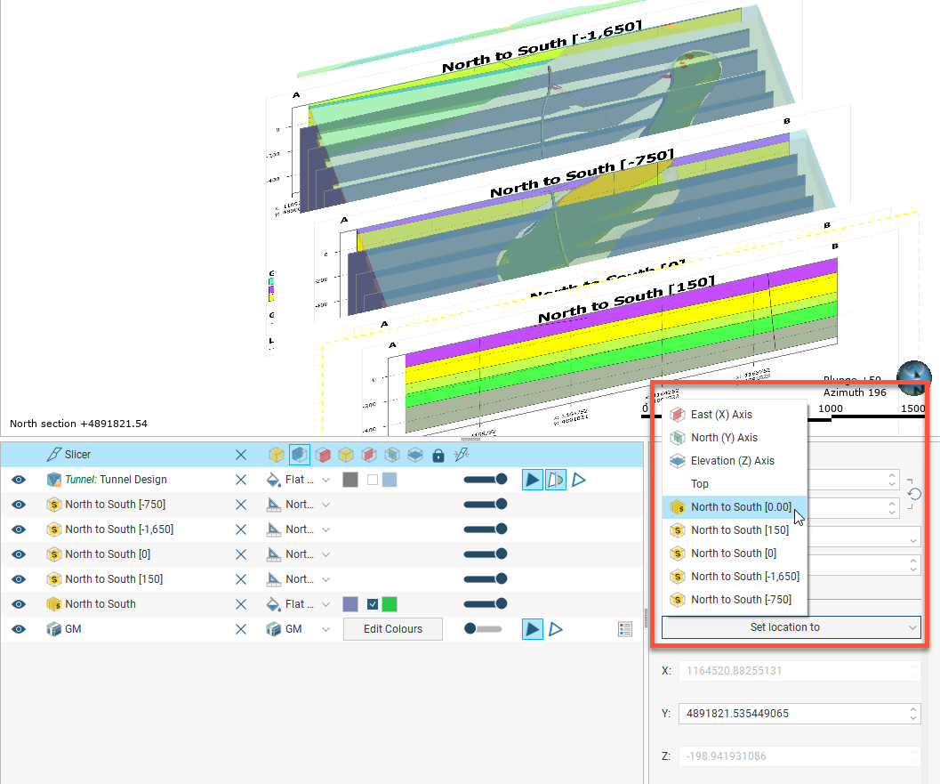
Next, set the Step size to the Spacing setting used to create the section. You can then use the , and . keys (these also have < and > on them) to go back and forwards to view each individual cross section.
You can also select any layout that has been added to the scene from the Set location to option list.
Exporting a Serial Section
Serial sections can be exported in the following formats:
- DXF Files (11/12 [AC1009]) (*.dxf)
- Drawing Files (2013/LT2013) (*.dwg)
- Bentley Drawing Files (v8) (*.dgn)
- Industry Foundation Classes 4.3 RC3 (*.ifc)
The DXF format exports a single file with a collection of DXF lines based on intersections between the selected evaluation and the section planes.
The offset sections that make up a serial section can also be exported as a PDF section layout. See Section Layouts for more information.
Got a question? Visit the Seequent forums or Seequent support
© 2022 Bentley Systems, Incorporated