Creating a MODFLOW Model
This feature is only available with the Hydrogeology extension. See Flow Models for more information.
To create a new MODFLOW model, you must first have at least one geological model defined in the project. Once this has been defined, add the geological model to the scene. Right-click on the Flow Models folder and select MODFLOW > New Structured Model. The New MODFLOW Model window will be displayed, together with controls in the scene that will help you to set the grid extents:
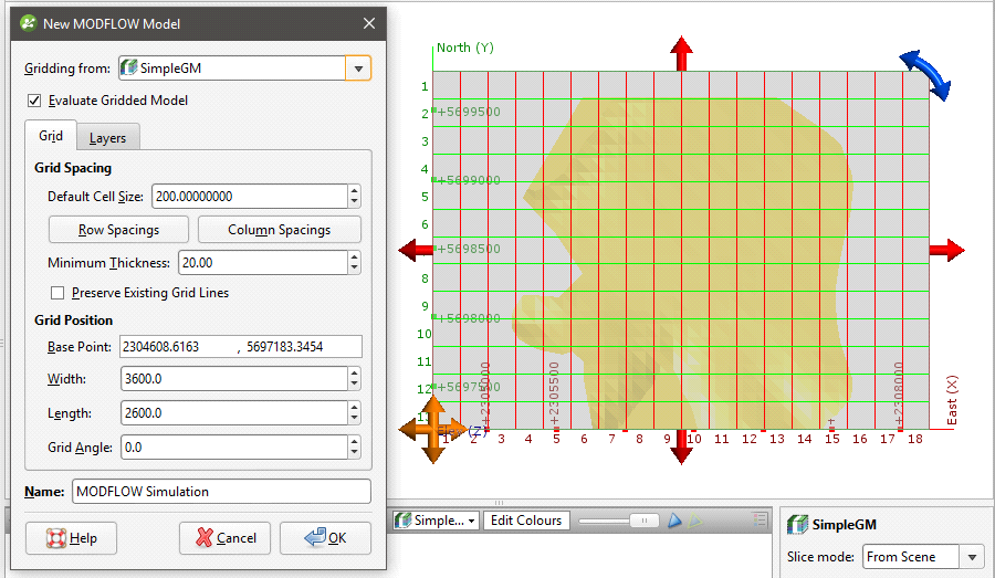
The new MODFLOW grid will be based on the geological model in the Gridding from setting. If you wish to use a geological model other than the one selected when the window is opened, select it from the list. The grid dimensions will be updated in the scene.
If the Evaluate Gridded Model box is ticked, the selected geological model will be evaluated on the new grid and set as the evaluation for export. If you do not wish to evaluate the geological model on the grid, untick the box. You will still be able to use the layers in the geological model to control the grid layers.
The Preserve Existing Grid Lines option is used when setting a non-uniform grid in the scene window. If you are going to define a non-uniform grid in this way, create the model with the Default Cell Size set to the smallest cell size you wish to use, then edit it as described in Editing a MODFLOW Model.
The grid should be slightly smaller than the selected geological model. Any MODFLOW cells that exist outside the geological model will be marked as inactive when the grid is exported to MODFLOW .
Horizontal Grid Spacing
By default, the horizontal grid for the model is uniform, with the size of each cell set by the Default Cell Size value. You can change the horizontal grid by editing row and column spacings. When you click on Row Spacings or Column Spacings, the Edit Spacings window will be displayed:
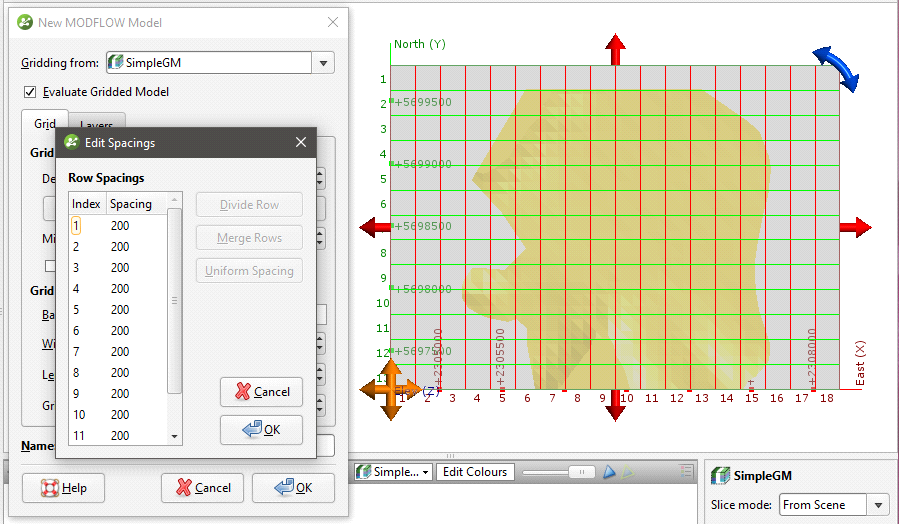
Changes made in the Edit Spacings window will be reflected in the scene.
There are four ways to change the spacings:
- Click on a value to edit it.
- Divide a row or column. Click on a row or column, then on the Divide Row or Divide Column button. Two new rows or columns will appear in the list.
- Merge rows or columns. Hold down the Shift key while clicking on each item, then click on the Merge Rows or Merge Columns button. The selected items will be combined.
- Set uniform spacing on selected rows or columns. You will be prompted to enter the number of cells you wish to create from the selected rows or columns.
Click OK.
For example, here, the rows and columns away from the model boundary have been divided to provide more detail. The different spacings are reflected in the scene:

Use close spacing for steep gradients and increase or decrease spacing gradually.
Vertical Grid Layering
The vertical grid layers are based on the geological model selected in the New MODFLOW Model window. Click on the Layers tab to view the layers:
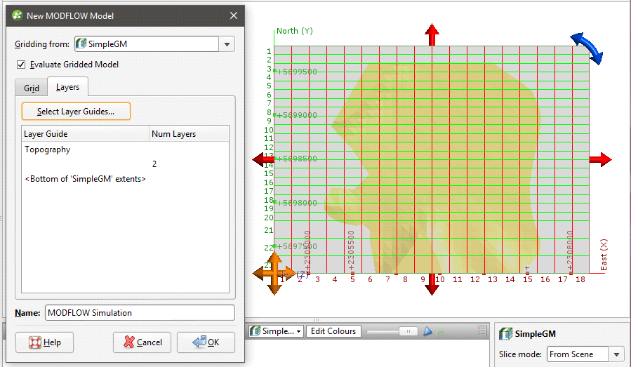
Initially, there are two layers equally spaced between the topography and the geological model. Change the layers by clicking on Select Layer Guides button. The Layer Guides window will appear, showing the layers available in the selected geological model:
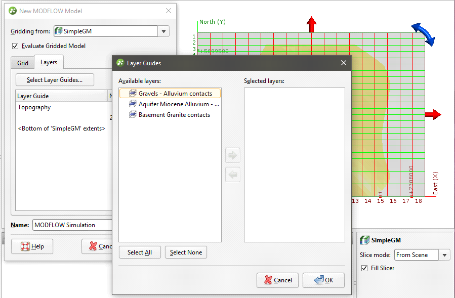
If the grid is required to follow a geological model lithology contact surface, move the layer into the Selected list and it will be honoured in the gridding process.
Click OK to return to the New MODFLOW Model window, in which the selected layers will be displayed:
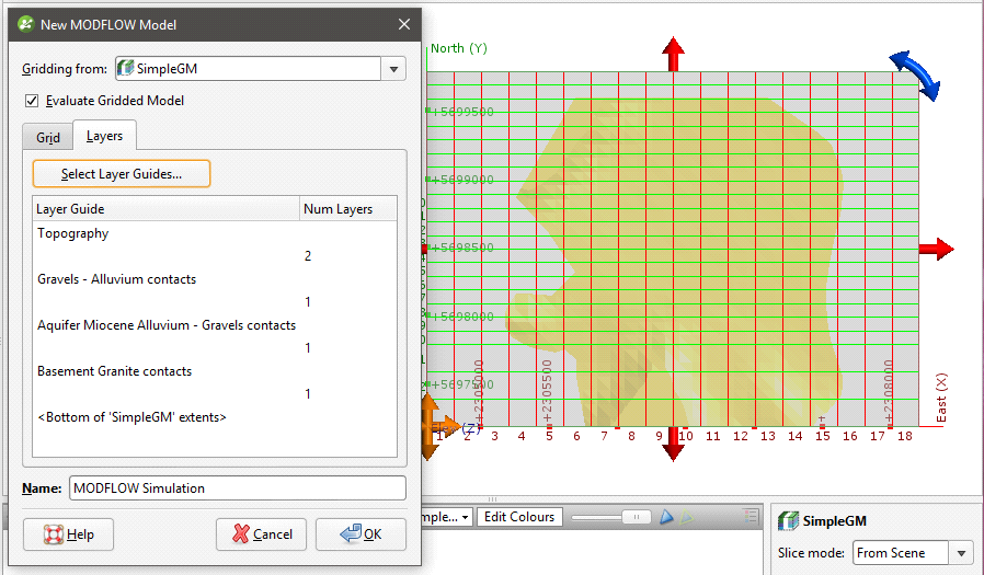
Click OK to create the new MODFLOW grid, which will appear in the Flow Models folder. You can edit the model by expanding it in the project tree and double-clicking on the grid object (![]() ). See Editing a MODFLOW Model.
). See Editing a MODFLOW Model.
For further information on working with the new model, see:
- MODFLOW Model Display
- MODFLOW Evaluations
- MODFLOW Hydrological Properties
- Head Values and MT3D Concentrations
- Generating a Head Value Mesh
- MODFLOW Model Export
Got a question? Visit the Seequent forums or Seequent support