
3D Planes and Surfaces - View and Modify Attributes
Use the Attributes tab to view and modify the properties of the individual 3D planes and surfaces in your 3D View. For more information on clipping, refer to the Modify 3D Clipping topic. For more information on the colour legend, refer to the Modify 3D Legend.
- How do you specify the Transparency of the plane or surface?
- How do you select the plane Offset (in Z units)?
- How do you display a grid using Smoothing ?
- How do you modify the following relief grid parameters (available only when a grid is included in the plane):
To specify the transparency of the plane:
The transparency of the plane can be adjusted interactively by moving the slider on the Transparency bar.
-
Using your cursor, move the slider on the Transparency bar
 .
.
-
To increase the transparency, slide the bar to the right and to decrease the transparency slide the bar to the left.
- True transparency is automatically enabled with video cards that support it.
To specify the plane offset in Z units:
-
In the Z Offset box, specify the offset value in ground units. Press the Enter key.
The plane will be redrawn in the 3D View with the new offset.
To display a grid using smoothing:
-
Select (
 ) the Smoothing check box, and the grid display will be smoothed interactively.
For display purposes, by default, the grid is first interpolated to a smooth image at the screen resolution. If you prefer to honour the grid resolution, leave the Smoothing option unchecked: the image will appear pixelated and the colour will change at the actual grid interval rather than the screen resolution.
This is only a change in how the grid is rendered or drawn; there is no change to the underlying data.
To specify the name of the relief grid:
-
Using either the drop-down list or the Browse button, locate and select the relief grid to modify.
To specify the base value of the relief grid:
-
In the Base box, specify the base value of the relief grid and press the Enter key.
The relief grid will be redrawn in the 3D View with the new base value.
To specify the vertical scale of the relief grid:
-
In the Scale box, specify the vertical scale of the relief grid and press the Enter key.
The relief grid will be redrawn in the 3D View with the new vertical scale.
To specify the Z range of the relief grid:
Using the Z Range text boxes or slider bars you can clip the Z range of the relief grid. The Z range can be modified interactively by moving the sliders or manually by specifying Z value ranges in the text boxes provided (minimum value on the left, maximum value on the right).
-
To manually specify the Z range , click inside the Z Range text boxes and specify the minimum and maximum values and press the Enter key.
The relief grid will be updated with the new Z range. -
To interactively modify the Z range, using your cursor move the bottom sliders (bottom inward-facing arrows) from either end of the slider bar, as shown in the image below:
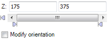
Your relief grid Z range will be updated interactively as you move the slider bars. Note that you can move the data range bar (centre bar), which will maintain the data range while interactively changing the relief grid data values. -
The sensitivity of the Z Range slider can be set enabling you to control the data increments.To set the sensitivity of the slider, click the drop-down menu (
 ) button
to the right of the Z Range text windows. The Sensitivity dialog
will be displayed.
) button
to the right of the Z Range text windows. The Sensitivity dialog
will be displayed.
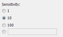
Using the radio buttons (
 )
select the increment value that best reflects your data, or specify a specific
value in the text box provided. This will close the dialog and set the sensitivity of the
current slider.
)
select the increment value that best reflects your data, or specify a specific
value in the text box provided. This will close the dialog and set the sensitivity of the
current slider.Move the slider and you will observe that the slider values move according to the selected sensitivity increments.
To specify the sample resolution of the relief grid:
-
The sample resolution of the relief grid can be set both interactively, using the slider bar or manually by specifying an exact value in the text box provided. You can specify a number up to 1152 (your entry will be converted to an even multiple of 16). Press the Enter key and the relief grid will be redrawn in the 3D View with the new sample resolution.
To reset the defaults of the relief grid:
-
The Defaults button resets the grid base and vertical scaling parameters to the "topographic" default values of 0.0 and 1.0. The clip limits are reset to the default values calculated from the relief grid.
To rescale the values of the relief grid:
-
Clicking the Rescale button resets the grid scaling parameters and clip limits to the default values calculated from the relief grid.
See Also:
Got a question? Visit the Seequent forums or Seequent support
© 2023 Seequent, The Bentley Subsurface Company
Privacy | Terms of Use