
Test Planned Survey Line of Sight
Use the Test Planned Survey Line of Sight option (geogxnet.dll(Geosoft.GX.UAVSurvey.LineOfSightCoverageCheck;Run)*) from the UAV Merge Sorties > Plan Survey menu to calculate what percentage of the subarea is visible from the takeoff location.
The option is available as Test Surveyed Line of Sight under the UAV Merge Sorties > Pre-processing menu.
Test Planned Survey Line of Sight dialog options
|
Survey name |
Select the survey you would like to work with from the list of available project surveys. Multiple surveys can be created within the same GPF. Script Parameter: PLAN_UAV_SURVEY.SURVEY_NAME |
|
Map name |
Provide the name of the map to display the coverage on. If a map with this name exists, it will be overwritten. Script Parameter: PLAN_UAV_SURVEY.MAP_NAME |
|
Select subarea |
Select the subarea for which you would like to calculate the line of sight coverage. Note that the project is cognisant of the subareas created thus far. Script Parameter: PLAN_UAV_SURVEY.SUBAREA |
|
Access points file |
In order to place the additional observers in accessible locations, you could optionally provide a .csv file with the X & Y locations of accessible points. These points will be plotted on the map for reference. You will still have to provide the coordinates for each observer location.
Script Parameter: PLAN_UAV_SURVEY.ACCESS_POINT_FILE |
|
Takeoff point coordinates |
The coordinates of the takeoff points cannot be modified in this tool. They are displayed for reference only. |
|
Terrain clearance |
Provide the height of the sensor above the terrain. This may already have been calculated as the drape channel; however, entering it here allows you to experiment and adjust the project parameters. Script Parameter: PLAN_UAV_SURVEY.TERRAIN_CLEARANCE |
|
Takeoff height |
If the pilot stands on the ground, enter the approximate height of the pilot’s eye level. If the pilot stands on an elevated platform, enter the height of the platform+ the pilot’s eye level height. Script Parameter: PLAN_UAV_SURVEY.TAKEOFF_HEIGHT |
Observer(s) |
Up to four additional observers can be provided for a given sortie. Observers can be very helpful if the survey area is of rugged topography and cannot be entirely visible to the pilot, regardless of where he may position himself. Observers can be in radio communication with the pilot, and as one observer (or pilot) loses sight of the drone as long as another observer has it in sight, the survey can continue.
|
|
Active |
You could provide the X, Y, Z coordinates for an observer; however, unless this box is checked, the observer will not factor into the line of sight calculation. Script Parameter: PLAN_UAV_SURVEY.ProjectName_SortieName_ACTIVE_ObserverIndex |
|
X & Y location |
Enter the location of the observer in ground coordinates. Script Parameters: PLAN_UAV_SURVEY.ProjectName_SortieName_X_ObserverIndex PLAN_UAV_SURVEY.ProjectName_SortieName_Y_ObserverIndex |
|
Observer height |
Specify the eye height of the observer above the terrain in the same units as the ground coordinates of the map. Script Parameter: PLAN_UAV_SURVEY.ProjectName_SortieName_HEIGHT_ObserverIndex |
|
[Locate] |
Click on this button to define the location of the observer on a plan map. Use the shortcut keys (or access them on the right mouse button menu) to navigate on the map before left-clicking on the location.
|
|
[Remove] |
Click on this button to remove an observer from the process. |
|
[Display Map] |
Click on this button to update and display the line of sight coverage on the current map and then come back to the dialog to continue adding/ editing observers. |
|
[OK] |
Click on this button to exit the tool and save the current parameters. |
Application Notes
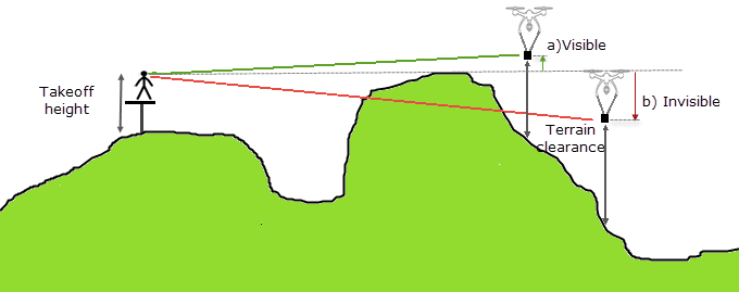
Given the DEM grid, a sortie GDB containing the path and a takeoff/ landing location for each XYZ point in the sortie path, this tool calculates an imaginary 3D straight line to the takeoff/ landing XYZ location (green and red lines in the illustration below). If this line is above the line of sight (dashed grey line), the sensor is visible. If the line is below the line of sight, it will not be visible. On the sortie plan map, the visible expanses are left blank while the areas that are not visible are colour coded according to the vertical distance of the drone from the line of sight (b) red arrow).
Output Files
The results are plotted on a plan map. The visible coverage is indicated in white. Points that are not visible are indicated with colour coded symbols along the path. In addition, the obstructed area is coloured as a function of the vertical depth of the drone from the line of sight. The % of points that are visible is reported.
You can modify the takeoff location and/ or the drone height and try again until the acceptable parameters are obtained.
*The GX.NET tools are embedded in the geogxnet.dll file located in the "...\Geosoft\Desktop Applications \bin" folder. If running this GX interactively, bypassing the menu, first change the folder to point to the "bin" directory, then supply the GX.NET tool in the specified format. See the topic Run GX for more details on running a GX.NET interactively.
Got a question? Visit the Seequent forums or Seequent support
© 2024 Seequent, The Bentley Subsurface Company
Privacy | Terms of Use