
Grid Math
Use the Grid and Image > Grid Math menu option (geogxnet.dll(Geosoft.GX.MathExpressionBuilder.MathExpressionBuilder;RunGrid)*) to create, save, load, and execute mathematical expressions for your grid data. This intuitive, standardized dialog provides all math expression tools in a single, tabbed interface.
Grid Math dialog options
|
Step 1: Enter a Mathematical Expression In the Expression box, enter your expression manually or construct it using the tabs and buttons below the box. |
|
|
Expression |
Expressions follow C-style syntax and may include a combination of functions and operators, absolute or variable grid names, reserved variables, DUMMY values, and numbers. Multiple equations are supported. (See examples in the Application Notes.) You may type directly or use the Variable & Operators and Functions tabs for assistance. For further guidance, see the Expression section in the Application Notes. |
|
|
Click the toggle to expand and view the available Operators and Functions. Use your keyboard to enter numerical values. Click on the links below to explore the tools and available tabs:
|
|
|
Click this button to insert a new grid variable at the cursor's location in the Expression box. The variable grid naming convention is G#, where # is the next available number. Do not confuse this with temporary variables (see Common Keys), which exist only at runtime and are not saved.
|
|
Step 2: Assign Grids Assign grid files to the variable names used in the expression. |
|
|
Assign grids |
This box is populated with all grid variables used in the Expression box. Each variable can be set either by choosing a grid from the drop-down list showing grids from the current project or by using the Browse button to locate and assign a different grid. The tool distinguishes between input and output grids:
See the Assign Grids section in the Application Notes for more guidance. |
|
Common tasks |
Use the drop-down list to insert predefined expressions to accelerate your workflow:
You can modify any selected expression further as needed. G0 = (condition)?G2:G3, the data type of the rightmost value, G3, determines the output data type.
|
|
Expression file |
Once your expression is complete, you can:
Expression files are saved in plain ASCII format and can be opened in any text editor outside of Oasis montaj. |
|
|
Click Clear to reset all input fields including the expression, grid assignments, and loaded file. |
|
|
Click Apply to execute the expression without closing the dialog–useful for applying it to multiple grids in sequence. |

 character and must be selected from the list.
Application Notes
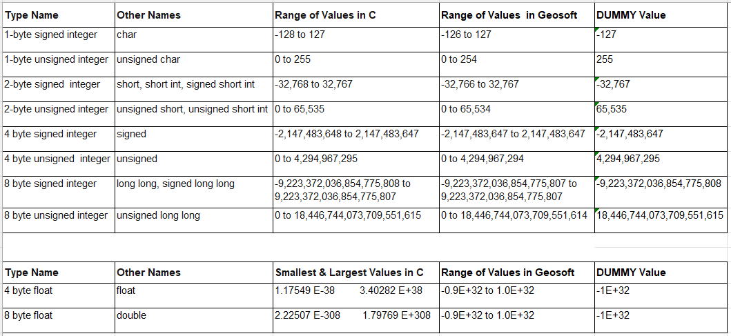
If an equation produces a value outside the data range, the output is set to DUMMY.
In Geosoft conventions, the DUMMY value depends on the data type:
-
Signed integer data types: The DUMMY value is set to the minimum value of the corresponding data range.
-
Unsigned integer data types: The DUMMY value is set to the maximum value of the corresponding data range.
-
Floating-point data types: The DUMMY values and data ranges for floating data types do not follow the above conventions. Instead, their values are set outside typical geophysical processing ranges.
Expression
Expressions are parsed from right to left. For example, in the conditional expression G0 = (condition)?G2:G3, the data type of the rightmost channel, G3, determines the output data type.
Longer, more complex expressions that span multiple lines remain fully visible as you work. When new rows are added to the Expression box, its height automatically expands—up to a maximum of 12 lines. Beyond this, a scroll bar appears along the right margin for navigation.
To further increase the height of the box, focus on the Expression box, hover your cursor over the top or bottom edge of the dialog until the double arrow appears, then click and drag the edge of the dialog to resize the box accordingly.
The dialog can also be widened for better visibility when working with long expressions. Hover over the left or right edge of the dialog until the double arrow appears, then click and drag to adjust the width as needed.
Assign Grids
To further increase the vertical height of the Assign grids box, click on an editable entry within the box until it becomes underlined, indicating that it is in focus. Then, hover the cursor over the top or bottom edge of the dialog until a double-headed arrow appears. Click and drag the edge to resize the dialog, which will also adjust the height of the Assign grids box. Note that clicking elsewhere inside the box will not activate the desired resizing function.
Temporary variables do not appear in this window.
Using Spatial Coordinates (X, Y, Z) as Grid Math Variables
Since Oasis montaj is spatially aware, location coordinates can be directly accessed using the “reserved” variable designations X, Y, and Z .
-
Use X and Y for a plan grid
-
Use X and Z or Y and Z for a straight section
-
Use and X, Y and Z for a curvilinear section
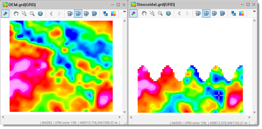
The example below uses the reserved coordinates X and Y of a plan grid to generate a sinusoidal masking pattern. The accompanying image illustrates the resulting masked grid.
//G0=.\Sinusoidal.grd(GRD)//G1=.\DEM.grd(GRD)G0 =(Y>(sin_deg((X-454000)/700*180)*500+5443000))?DUMMY:G1;
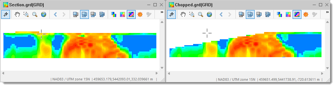
The following example shows a Grid Math expression that uses the Y and Z coordinates as variables to partially mask a section grid along a slope. The image below illustrates the resulting section grid.
//G0=.\Chopped.grd(GRD)//G1=.\Section.grd(GRD)G0 =(Z>(Y-5440800)/6-200)?DUMMY:G1;
Temporary Variable Definition
Temporary variables can be defined within a math expression. These variables exist only during computation and are not saved in the output. To define one, prefix the variable name with an "@" symbol (e.g., @Var1). You can include multiple temporary variables into a single expression.
*The GX.NET tools are embedded in the geogxnet.dll file located in the \Geosoft\Desktop Applications\bin folder. To run this GX interactively (outside the menu), first navigate to the bin directory and provide the GX.NET tool in the specified format. See the Run GX topic for more guidance.
Got a question? Visit the Seequent forums or Seequent support
Copyright (c) 2025 Bentley Systems, Incorporated. All rights reserved.
Privacy | Terms of Use