
Remove Aircraft and Cosmic Effects
Use the RPS > Remove Aircraft and Cosmic Effects option (geogxnet.dll(Geosoft.GX.Radiometrics.RemoveAircraftAndCosmicEffects;Run)*) to remove aircraft and cosmic background contributions and produce background-corrected airborne radiometric data. For more details, refer to the Application Notes below.
To rerun the process with previous settings, select the header cell of any channel generated by this operation, then right-click to open the context menu. The last item in the menu is the most recently executed process (GX). Select it to reopen the associated dialog. From there, you can rerun the process using the existing settings, adjust parameters before execution, or simply close the dialog. Learn more about Dynamic Process Links (Makers).
Remove Aircraft and Cosmic Effects dialog options
|
Input channel suffix |
Suffixes from channels generated by earlier processes (Along-Line Filtering, Account for Dead Time, or Generate Radioelement Counts) are automatically detected and listed.
By default, the suffix from the most recent process is preselected. Once you select a suffix, the associated channels are listed below the field. Script Parameter: SPECTRO.REMOVE_AIRCRAFT_AND_COSMIC_EFFECTS_INPUT_SUFFIX |
|
Correction Coefficients - Aircraft and Cosmic Specify the aircraft background and cosmic stripping values for your instrument configuration or survey characteristics. These values are retained after you run the tool and will be available the next time the dialog is opened. See the Application Notes below for details. |
|
|
Potassium (K) |
Enter the aircraft and cosmic correction coefficients for the potassium (K) data. Script Parameters: SPECTRO.KAIRBACK SPECTRO.KCOSSTRIP |
|
Uranium (eU) |
Enter the aircraft and cosmic correction coefficients for the equivalent uranium (eU)* data. Script Parameters: SPECTRO.UAIRBACK SPECTRO.UCOSSTRIP |
|
Thorium (eTh) |
Enter the aircraft and cosmic correction coefficients for the equivalent thorium (eTh)* data. Script Parameters: SPECTRO.THAIRBACK SPECTRO.THCOSSTRIP |
|
Total count (TC) |
Enter the aircraft and cosmic correction coefficients for the total count (TC) data. Script Parameters: SPECTRO.TCAIRBACK SPECTRO.TCCOSSTRIP |
|
Upward Uranium (UpU) |
Enter the aircraft and cosmic correction coefficients for the upward uranium (UpU) data. If the channel does not exist, this field will be disabled (greyed out). Script Parameters: SPECTRO.UPAIRBACK SPECTRO.UPCOSSTRIP |
|
* Refer to the Radioactive Decay and Gamma Ray Emission section under Application Notes for more details.
|
|
|
Output channel suffix |
Enter a suffix to append to output channels. Default: As you type, the information string below the field updates to show the resulting channel names. Each name is formed by combining the radiometric element name with the suffix (letters and numbers only). Output channels follow the pattern element_suffix. Script Parameter: SPECTRO.REMOVE_AIRCRAFT_AND_COSMIC_EFFECTS_OUTPUT_SUFFIX |
Application Notes
This tool operates on pre-processed channels generated by Along-Line Filtering, Account for Dead Time, or Generate Radioelement Counts. It applies aircraft and cosmic background corrections to these inputs and produces background‑corrected output channels, labeled *_bg by default.
Radioactive Decay and Gamma Ray Emission
Potassium concentrations in rocks and soils are commonly estimated using gamma‑ray spectrometry, which detects the 1461 keV gamma rays emitted by the radioactive isotope potassium-40 (40K). Unlike 40K, which decays directly to a stable daughter isotope, uranium‑238 (238U) and thorium-232 (232Th) decay through long chains of intermediate, unstable daughter products.
For gamma-ray spectrometry, the energies associated with these decay series are identified through their most prominent daughter isotopes:
-
238U → 214Bi (bismuth)
-
232Th → 208Tl (thallium)
Characteristic gamma‑ray energy peaks — most notably the 1765 keV line from 214Bi and the 2615 keV line from 208Tl — serve as markers for the uranium and thorium decay chains. The intensities of these emissions are then scaled to estimate concentrations of uranium and thorium, reported as equivalent uranium (eU) and equivalent thorium (eTh).
Cosmic and Aircraft Background Corrections
Cosmic background radiation results from high-energy cosmic ray interactions with the atmosphere. The intensity of cosmic rays increases with altitude—approximately doubling every 2,000 meters—and exhibits minor variations with latitude.
In addition to cosmic radiation, background radiation is also generated by the aircraft and its onboard equipment. This is due to trace amounts of naturally occurring radioactive elements such as potassium, uranium, and thorium present in the materials used in the aircraft and its systems.
Cosmic radiation intensity increases with altitude, while the aircraft’s spectral contribution is assumed to be constant with a distinct energy spectrum.
High-Altitude Cosmic Background Flights
The aircraft’s spectral contribution is assumed to be constant. The cosmic spectrum at each observation point is estimated by scaling a normalized cosmic spectrum by the cosmic window count rate. Each measured spectrum represents the sum of the aircraft component (constant) and the cosmic component, both of which are then subtracted from the total gamma-ray counts.
Over open water, contributions from ground sources and atmospheric radon are minimal. To estimate the aircraft spectrum and the normalized cosmic spectrum, high-altitude flights are performed offshore, ideally in regions with low radon concentrations. Measurements are taken at multiple altitudes (e.g., 1.0, 1.5, 2.0, 2.5, and 3.0 km above sea level), with background count rates recorded across all energy channels. At each altitude, data is collected for a minimum of 2 minutes and up to 15 minutes, and then averaged.
Aircraft and Cosmic Spectra
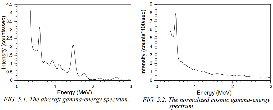
The measured spectra are each the sum of the aircraft component (constant) and the cosmic component. Since in the energy range of interest (700 to 3072 keV), the count rate in the cosmic window is linearly related to the count rate in the i‑th energy channel, a linear regression of the cosmic window count rate against a given channel yields the cosmic sensitivity (slope of regression) and the vessel background (zero intercept) for that channel as follows:
-
Slope (b): Cosmic sensitivity
-
Intercept (a): Aircraft (vessel) background
For each of the 4 count windows, a least-squares (LSQ) linear fit is applied to determine the slope (b) and intercept (a) [1]:

where:
-
Ni — Aircraft + cosmic background count rate in the i'th channel
-
ai — Aircraft background contribution in the i‑th channel
-
bi — Cosmic background contribution in the i‑th channel, normalized to unit counts in the cosmic window
-
ncos — Cosmic window count rate
The illustration below of aircraft and cosmic spectra is taken from the referenced IAEA document [1] (p. 61).
Aircraft background contributions can vary significantly between different aircraft.
Cosmic stripping factors are largely independent of the number of detector packages but may vary slightly across installations.
Reviewing Results
Once processing is complete, review the raw, filtered, levelled, and corrected channels in the profile window to assess the impact of each correction step. If the results are unsatisfactory, adjust the parameter values and rerun the GX.
*GX.NET tools are embedded in the geogxnet.dll file located in the \Geosoft\Desktop Applications\bin folder. To run this GX interactively (outside the menu), navigate to the bin directory and specify the GX.NET tool in the required format. See the Run GX topic for more guidance.
References
- [1] G. Erdi-Krausz et al. (2003), Guidelines for Radioelement Mapping Using Gamma Ray Spectrometry Data, IAEA-TECDOC-1363, International Atomic Energy Agency.
https://www-pub.iaea.org/MTCD/Publications/PDF/te_1363_web.pdf
Got a question? Visit the Seequent forums or Seequent support
Copyright (c) 2026 Bentley Systems, Incorporated. All rights reserved.
Privacy | Terms of Use