Intrusions
This topic describes creating and editing intrusions. The topic is divided into:
- Creating Intrusions
- Intrusions in the Project Tree
- Displaying Intrusion Points
- Refining Intrusions
- Surfacing Options for Intrusions
- Applying a Trend to an Intrusion
- Clipping Values for Intrusions
- Interpolation Settings
For a general introduction to how intrusions interact with other contact surfaces, see Intrusion Contact Surfaces in Contact Surfaces.
Creating Intrusions
Lithology data is often the most reliable data source to use when building geological surfaces, and it is best to derive contact surfaces from lithology data when it is available. If no lithology data is available, you can create intrusions from other data in the project.
One thing to keep in mind for all intrusion contact surfaces is that an intrusion removes all the existing material on the younger side of the contact surface. Therefore:
- An intrusion should always have the younger side of its surface labelled with the intruded material. This is called the “interior lithology”.
- The older side will typically be labelled “Unknown” as an intrusion will usually displace multiple older lithologies. This is called the “exterior lithology”.
Intrusions from Lithology Contacts
Lithology data is often the most reliable data source to use when building geological surfaces, and it is best to derive contact surfaces from lithology data when it is available. There are two ways to create intrusions from lithology data:
- Using the base lithology column assigned when the model was created.
- Using other lithology information available in the project. This is useful when you have created an additional lithology column as part of correcting and working with the drillhole data. For example, if when building a geological model it becomes apparent that changes need to be made to the drillhole data, you can import additional data or create a new column using the split lithology, group lithology or interval selection tools.
To create a new intrusion from lithology contacts, right-click on the Surface Chronology object and select either New Intrusion > From Base Lithology or New Intrusion > From Other Contacts. The only difference in the two methods is that when creating an intrusion from other contacts, you must first select the lithology column from those available in the project and specify the First lithology and the Second lithology.
Select the intrusive lithology as the interior lithology. Other lithologies will be displayed in the Exterior lithologies list. Drag any younger lithologies to the Ignore list.
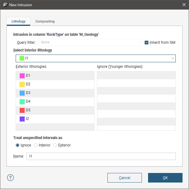
Unspecified intervals are intervals that have no data. By default, unspecified intervals are ignored when creating an intrusion, but you can also treat them as the interior lithology or as exterior lithologies.
Sometimes intrusive boundaries are poorly defined, with fragments of country rock intermixed with the intrusive body. This can result in very small segments near the edges of the intrusion. Modelling the fine detail is not always necessary, and so compositing can be used to smooth these boundaries. Compositing parameters are set in the Compositing tab:
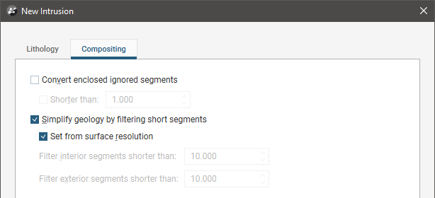
The settings in this tab are described in Category Composites.
Click OK to create the intrusion, which will be added to the project tree as part of the Surface Chronology object.
Intrusions from Other Data
If suitable lithology data is not available, intrusions can be created from other data in the project, such as GIS data, structural data, points, polylines and surfaces. The steps for creating intrusions from other data are similar, regardless of the data used to create the surface:
- Right-click on the Surface Chronology and select one of the data types from the New Intrusion menu.
- Select the data object that will be used to define the surface. This must already be in the project, unless you are using a polyline, in which case you are given the option to create a new polyline.
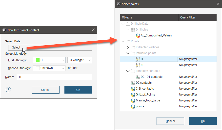
- Select the First lithology and Second lithology. These are the lithologies that will be assigned to each side of the contact surface. The lithologies you can choose from are those defined for the geological model in the Lithologies object (see Model Lithologies).
- Set whether the First lithology is older or younger than the Second lithology. Leapfrog Geo will, by default, put the younger side of a contact surface up, but this can be changed later.
Here, a points data object is being used to create an intrusion:
For polylines, you first set the lithologies and the younging order, then click OK to move on to the next step:
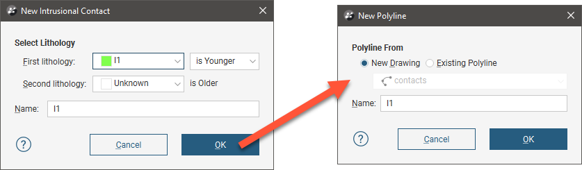
You can draw the polyline in the scene directly by selecting the New Drawing option. You can also use any polyline in the project by selecting the Existing Polyline option. You can then select the required polyline from the list.
The new intrusion will appear in the project tree under the Surface Chronology. Add the contact surface to the scene to view it and check that it is oriented correctly.
Expand the surface in the project tree to see how it was made.
If creating a surface from a new polyline, the polyline will not be able to be used elsewhere in the project unless it has been shared. To share the polyline, expand the contact surface in the project tree, right-click on the polyline and select Share. The polyline will then be available elsewhere in the project.
As further refinements are made to the surface, that information will also be added to the contact surface in the project tree.
Intrusions in the Project Tree
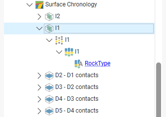
The name Leapfrog Geo automatically assigns to an intrusion is the name of the intrusive lithology. In the project tee, expand the intrusion to see how it was made:
Double-click on the intrusion to edit it. Double-click on the points object (![]() ) to edit the intrusion lithology, change compositing parameters and change point generation options.
) to edit the intrusion lithology, change compositing parameters and change point generation options.
As further refinements are made to the surface, that information will also be added to the project tree. See Refining Intrusions below for more information.
Displaying Intrusion Points
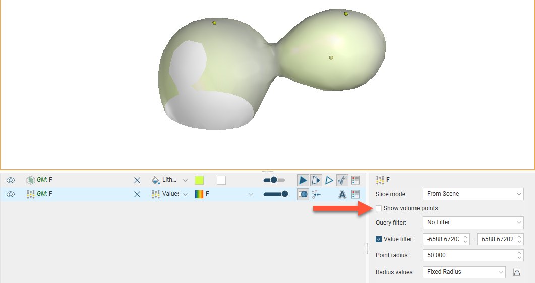
When you view the intrusion points in the scene, you can display only the contact points or all the points used in creating the intrusion. To display all points, click on the points object (![]() ) in the shape list and tick the box for Show volume points. Here, only the contact points are displayed:
) in the shape list and tick the box for Show volume points. Here, only the contact points are displayed:
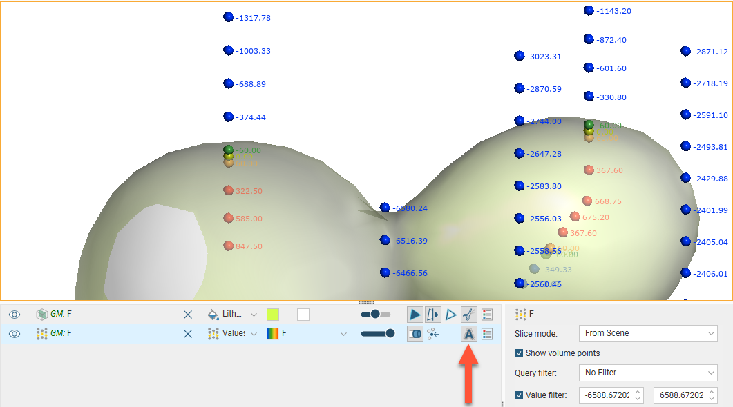
When the volume points are displayed, points with negative values are those outside the surface, while points with positive values are those inside. Show text (![]() ) has been enabled in the shape list so that the values are displayed:
) has been enabled in the shape list so that the values are displayed:
You can change the way intrusion points are generated by double-clicking on the points object (![]() ) in the project tree. See Intrusion Point Generation Parameters.
) in the project tree. See Intrusion Point Generation Parameters.
Refining Intrusions
You can refine intrusions in several ways:
- Add other data. Right-click on the surface to see the options available, which will depend on how the surface was created. See Adding Data to Surfaces for more information.
- Edit the surface with a polyline. Right-click on the surface in the project tree and select either Edit > With Polyline. See Editing Surfaces With Polylines for more information.
- Edit the surface using structural data. Right-click on the surface and select Edit > With Structural Data. See Editing Surfaces With Structural Data for more information.
To edit an intrusion’s settings, double-click on it in the project tree. In the Lithologies tab, change the lithologies assigned to each side of the surface, if required.
Surfacing Options for Intrusions
Surfacing options for an intrusion can be changed by double-clicking on the surface in the project tree and then clicking on the Surfacing tab. There are additional settings related to boundary filtering and snapping to data in the Inputs tab.
Boundary Filtering
When data objects are added to a surface, there are two ways to handle the data that lies outside the surface’s boundary:
- Filter the data. The surface is only influenced by the data that falls inside the surface’s boundary.
- Leave the data unfiltered. The surface is influenced by the data both inside and outside the surface’s boundary.
The boundary of an intrusion can be the geological model boundary or a fault block boundary.
The Boundary filter setting determines how data used to define the surface is filtered:
- Off. Data is not filtered.
- All data. All data is filtered.
- Drilling only. Only drillhole data and data objects derived from drillhole data are filtered.
- Custom. Only the data objects specified in the Inputs tab are filtered.
Snapping to Data
Often, surfaces should honour drillhole data and treat data objects such as polylines and GIS data as interpretations, as discussed in Honouring Surface Contacts.
There is a Snap to data setting for a geological model as a whole that is set in the Geological Model > General tab (see Editing a Geological Model). Snap to data can also be set on a surface-by-surface basis by double-clicking on the surface in the project tree and then clicking on the Surfacing tab.
For individual contact surfaces, the options are:
- Inherit from GM. The setting for the geological model as a whole is used. This is the default setting.
- Off. Surfaces do not snap to the data used to create them.
- All data. Surfaces snap to all data within the Maximum snap distance, which includes drillhole data and any data added to the surfaces.
- Drilling only. Surfaces snap to drillhole data and data objects derived from drillhole data within the Maximum snap distance but not to other data used to modify the surfaces.
- Custom. Surfaces snap to the data objects indicated in the Inputs tab for each surface.
Take care in enabling snapping and in selecting what data the surface will snap to, as the more data you include, e.g. by setting a large Maximum snap distance or selecting All data for Snap to data, the greater the possibility that errors in the data or assumptions inherent in interpretations (e.g. polylines) will cause distortions in the meshes. If you do enable snapping, it is best to snap only to drilling data. See Honouring Surface Contacts for more information on these settings.
If you need a surface to honour drillhole data but treat other data objects as interpretations, select Drilling only. To honour some data objects while treating others as interpretations, select Custom, then click on the Inputs tab to enable snapping for individual objects.
Surface Resolution
See Surface Resolution for a Geological Model for information about the surface resolution settings in the Surfacing tab.
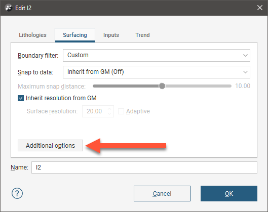
Clicking Additional options adds Value Clipping and Interpolant tabs to the window and also allows the use of a structural trend in the Trend tab:
These are described in Applying a Trend to an Intrusion, Clipping Values for Intrusions and Interpolation Settings below.
Applying a Trend to an Intrusion
There are two ways to change the trend for an intrusion:
- Right-click on the surface in the project tree and select Adjust Surface.
- Double-click on the surface in the project tree and then click on the Trend tab.
See Global Trends for more information.
You can also use a structural trend for an intrusion. To do this, click the Additional options button in the Surfacing tab, then click on the Trend tab.
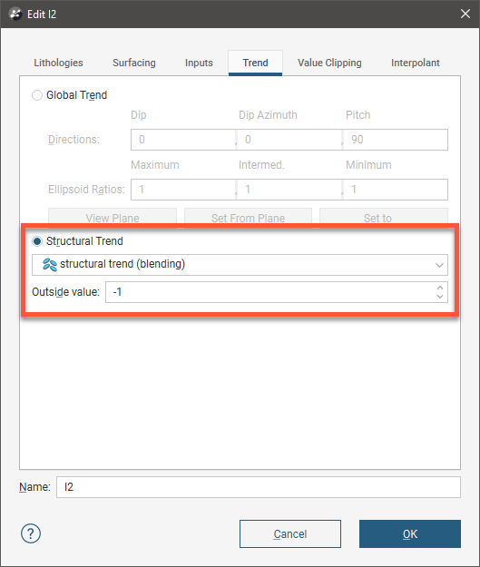
Click on Structural Trend, then select the required trend from the list. See Structural Trends for more information.
Clipping Values for Intrusions
You can change settings for intrusions by double-clicking on the contact surface in the project tree. The Value Clipping tab is only available for intrusion contact surfaces.
In the Value Clipping tab, you can manipulate the data distribution by clipping the data:
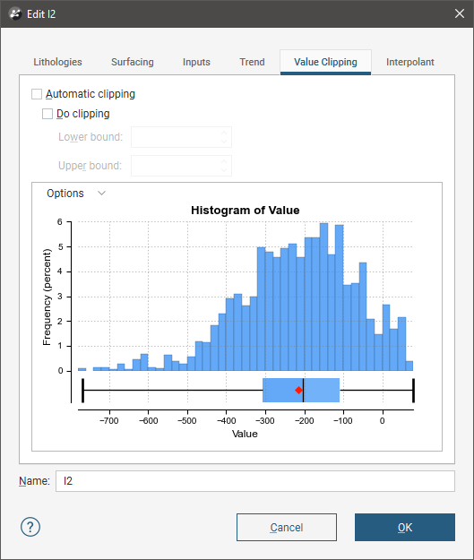
Clipping caps values that are outside the range set by the Lower bound and Upper bound values. For example, if you change the Upper bound from 16.00 to 10.00, distance values above 10.00 will be regarded as 10.00.
The Automatic clipping setting has different effects based on whether a global trend or structural trend is set in the Trend tab:
- When a global trend is applied, Leapfrog Geo automatically clips the values. That is, the Automatic clipping setting is Do clipping and Leapfrog Geo sets the Lower bound and Upper bound from the data. To disable clipping, untick Automatic clipping, then untick Do clipping. To change the Lower bound and Upper bound, untick Automatic clipping, then change the values.
- When a structural trend is applied, Leapfrog Geo automatically does not clip the values. To clip values, untick Automatic clipping, then tick Do clipping. Again, Leapfrog Geo sets the Lower bound and Upper bound values from the data and you can change them, if required.
Interpolation Settings
You can change settings for an intrusion by double-clicking on the intrusion in the project tree and clicking on the Interpolant tab. For more information on the settings in this tab, see the Interpolant Functions topic.
Got a question? Visit the Seequent forums or Seequent support