
Compton Stripping
Use the RPS > Compton Stripping option (geogxnet.dll(Geosoft.GX.Radiometrics.ComptonStripping;Run))*) to correct airborne radiometric data for spectral overlap effects ("stripping"). For additional information, refer to the Application Notes below.
To rerun the process with previous settings, select the header cell of any channel created by the process, then right-click to open the context menu. The last item in the menu represents the most recently executed process (GX). Select it to reopen the associated dialog. From there, you can rerun the process with the existing settings, adjust parameters before execution, or simply close the dialog. Learn more about Dynamic Process Links (Makers).
Compton Stripping dialog options
|
Input channel suffix |
If Remove Radon Effect has been run on the current database, the suffix for the generated channels is automatically detected and preselected. If multiple sets exist, all suffixes are listed, with the most recent one selected by default. Once a suffix is chosen, the associated channels are listed below the field. Script Parameter: SPECTRO.COMPTON_STRIPPING_INPUT_SUFFIX |
|
STP altitude channel |
Select the STP-corrected altitude. Default name: RALTSTP Script Parameter: SPECTRO.RALTSTP |
|
Stripping Ratios Specify the spectral stripping ratios by entering new values or accepting the displayed defaults. See the Application Notes for more details. |
|
|
alpha |
Specify the α spectral ratio. Default: 0.24 Script Parameter: SPECTRO.ALPHA |
|
beta |
Specify the β spectral ratio. Default: 0.37 Script Parameter: SPECTRO.BETA |
|
gamma |
Specify the γ spectral ratio. Default: 0.7 Script Parameter: SPECTRO.GAMMA |
|
a |
Specify the a spectral ratio. Default: 0.05 Script Parameter: SPECTRO.ASTRIP |
|
b |
Specify the b spectral ratio. Default: 0 Script Parameter: SPECTRO.BSTRIP |
|
g |
Specify the g spectral ratio. Default: 0 Script Parameter: SPECTRO.GSTRIP |
|
Output channel suffix |
Specify the suffix to append to output channels. Default: As you type, the information string below the field updates to reflect the new output channel names. Script Parameter: SPECTRO.COMPTON_STRIPPING_OUTPUT_SUFFIX |
Application Notes
In airborne gamma-ray spectrometry, the energy spectra of potassium (K), uranium (U), and thorium (Th) naturally overlap. As a result, each spectral window—intended to isolate a specific radioelement—also detects gamma rays from the other two.
-
Gamma rays from the thorium decay series appear in both the uranium and potassium windows.
-
Gamma rays from the uranium decay series appear in the potassium and thorium windows.
Correcting Spectral Overlap: Stripping
In airborne gamma-ray spectrometry, correcting for spectral overlap is known as stripping. To isolate the true signal from each radioelement, a correction process called spectral stripping is applied. This ensures that the recorded counts in the K, U, and Th windows reflect only their respective elemental contributions—free from contamination by overlapping spectra.
What Are Stripping Ratios?
Stripping ratios are spectral correction factors used to adjust the count rates in each window for cross-element interference. They quantify how much signal from one element appears in another element’s window when measured from pure sources of K, U, and Th.
These ratios are denoted as:
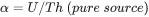
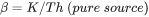
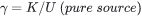
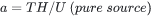

Where:
α (Th into U): Ratio of counts in the U window to those in the Th window for a pure Th source
a (U into Th): Reverse ratio; counts in the Th window to those in the U window for a pure U source
β (Th into K): Ratio of counts in the K window to those in the Th window for a pure Th source
b (K into Th): Reverse ratio; counts in the Th window to those in the K window for a pure K source
γ (U into K): Ratio of counts in the K window to those in the U window for a pure U source
g (K into U): Reverse ratio; counts in the U window to those in the K window for a pure K source
How Are Stripping Ratios Determined?
Stripping ratios are empirically derived using specially constructed calibration pads containing known concentrations of K, U, and Th. These calibration measurements are typically performed and provided by the instrument manufacturer. Additionally, spectrometers are periodically returned to the manufacturer for recalibration and measurement.
Altitude Corrections
Due to changes in gamma-ray attenuation and scattering with altitude, the three primary stripping ratios —α, β, and γ—exhibit a systematic increase with elevation above ground level. To account for this, corrections are applied based on the STP equivalent altitude.
In airborne surveys, it is standard practice to measure these stripping ratios at ground level and then calculate their increase at the actual flight altitude. The corrections factors per metre of altitude are shown below.
Increase in stripping ratios with altitude (after IAEA, 1991 [2]):
Stripping Ratio Increase per Metre α 0.00049 β 0.00065 γ 0.00069
Reverse stripping ratios (a, b, and g) are generally small and do not require altitude correction.
Applying Stripping Ratios
The stripping process involves two key steps:
-
Ratio Calculation: The α, β, and γ stripping ratios are corrected for each record based on the STP equivalent altitude.


Where:
he = equivalent height AGL (above ground level) at STP
-
Spectral Stripping: The adjusted ratios are then used to perform spectral stripping—that is, to separate the true elemental contributions in each window.
 Expand to see the calculated stripped count rates in the Potassium, Uranium and Thorium
channels.
Expand to see the calculated stripped count rates in the Potassium, Uranium and Thorium
channels.


Where:
KSTRIP = Output Compton stripped potassium
USTRIP = Output Compton stripped uranium
THSTRIP = Output Compton stripped thorium
And where:
KLEVL = Input potassium levelled count channel
ULEVL = Input uranium levelled count channel
THLEVL = Input thorium levelled count channel
BK = ALPHA2*GAMMA2-BETA2;
CK = ASTRIP*BETA2-GAMMA2;
DK = 1-ASTRIP*ALPHA2;
BU = GSTRIP*BETA-ALPHA
CU = 1-BSTRIP*BETA
DU = BSTRIP*ALPHA-GSTRIP
BTH = 1-GSTRIP*GAMMA2;
CTH = BSTRIP*GAMMA2-ASTRIP;
DTH = ASTRIP*GSTRIP-BSTRIP;
Where:
ALPHA2 = ALPHA + 0.0004895*RALTSTP
BETA2 = BETA + 0.0006469*RALTSTP
GAMMA2 = GAMMA + 0.0006874*RALTSTP
And:
RALTSTP = Input STP corrected radar altimeter channel value (m)
ALPHA = Input Compton stripping alpha factor (default: 0.24)
BETA = Input Compton stripping beta factor (default: 0.37)
GAMMA = Input Compton stripping gamma factor (default: 0.70)
ASTRIP = Input Compton stripping a factor (default: 0.05)
BSTRIP = Input Compton stripping b factor (default: 0.0)
GSTRIP = Input Compton stripping g factor (default: 0.0)
And where:

*GX.NET tools are embedded in the geogxnet.dll file located in the \Geosoft\Desktop Applications\bin folder. To run this GX interactively (outside the menu), first navigate to the bin directory and provide the GX.NET tool in the required format. See the Run GX topic for more guidance.
References
- [1] G. Erdi-Krausz et al. (2003), Guidelines for Radioelement Mapping Using Gamma Ray Spectrometry Data, IAEA-TECDOC-1363, International Atomic Energy Agency.
https://www-pub.iaea.org/MTCD/Publications/PDF/te_1363_web.pdf - [2] IAEA (1991), Airborne Gamma Ray Spectrometer Surveying, Technical Reports Series No. 323, International Atomic Energy Agency.
https://inis.iaea.org/collection/NCLCollectionStore/_Public/22/072/22072114.pdf
Got a question? Visit the Seequent forums or Seequent support
Copyright (c) 2025 Bentley Systems, Incorporated. All rights reserved.
Privacy | Terms of Use