
Remove Radon Effect
Use the RPS > Remove Radon Effect option (geogxnet.dll(Geosoft.GX.Radiometrics.RemoveRadonEffect;Run)*) to correct airborne radiometric data for atmospheric radon background radiation. In addition to the upward-looking detector method, you can also choose the over-water survey method. For more details, see the Application Notes below.
To rerun the process with previous settings, select the header cell of any channel generated by this operation, then right-click to open the context menu. The last item in the menu is the most recently executed process (GX). Select it to reopen the associated dialog. From there, you can rerun the process using the existing settings, adjust parameters before execution, or simply close the dialog. Learn more about Dynamic Process Links (Makers).
Remove Radon Effect dialog options
|
Input channel suffix |
If Remove Aircraft and Cosmic Effects has been applied to the current database, the suffix used for the generated channels is automatically detected and preselected.
If multiple channel sets exist, all detected suffixes are listed, with the most recent one selected by default. Once you select a suffix, the associated channels are listed below this field. Script Parameter: SPECTRO.REMOVE_RADON_EFFECT_INPUT_SUFFIX |
|
Method |
Select the desired method:
Refer to the Application Notes below for further details. Script Parameter: SPECTRO.RADON_REMOVAL_METHOD [0: Upward looking detector; 1: Over water] |
Upward-Looking Detector Method |
|
|
Specify the cutoff values for low-pass filtering to smooth noisy data. To disable filtering for a specific channel, set its cutoff value to 0. See the Application Notes for more details. |
|
|
Upward U cutoff |
Enter a cutoff value for the upward uranium (UpU) channel. Typical value: 200 Script Parameter: SPECTRO.UPUSWAV_RADON |
|
eU cutoff |
Enter the equivalent uranium (eU)* cutoff value. Typical value: 200 Script Parameter: SPECTRO.UTSWAV_RADON |
|
eTh cutoff |
Enter the equivalent thorium (eTh)* cutoff value. Typical value: 200 Script Parameter: SPECTRO.THTSWAV_RADON |
|
Skyshine Coefficients Specify the skyshine coefficients for your instrument configuration or survey design. These values are retained after you run the tool and will be available the next time the dialog is opened. See the Application Notes for more details. |
|
|
A1 |
Enter a value for the A1 coefficient. Script Parameter: SPECTRO.UPA1 |
|
A2 |
Enter a value for the A2 coefficient. Script Parameter: SPECTRO.UPA2 |
|
Calibration Factors Specify the atmospheric radon calibration constants. These values are retained after you run the tool and will be available the next time the dialog is opened. See the Application Notes for more details. |
|
|
Potassium (K) |
Enter the a and b calibration constants for the potassium (K) data. Script Parameters: SPECTRO.UPAK SPECTRO.UPBK |
|
Uranium (eU) |
Enter the a and b calibration constants for the equivalent uranium (eU)* data. Script Parameters: SPECTRO.UPAU SPECTRO.UPBU |
|
Thorium (eTh) |
Enter the a and b calibration constants for the equivalent thorium (eTh)* data. Script Parameters: SPECTRO.UPAT SPECTRO.UPBT |
|
Total count (TC) |
Enter the a and b calibration constants for the total count (TC) data. Script Parameters: SPECTRO.UPAI SPECTRO.UPBI |
|
* Refer to the Radioactive Decay and Gamma Ray Emission section under Application Notes for more details.
|
|
Over Water Method |
|
|
Reference channel |
Select the over-water mask channel. Script Parameter: SPECTRO.WBREF |
|
Filter cutoff |
Enter the filter cutoff value. Choose a filter width that matches the average length of the over‑water segments, but avoid selecting a window so long that it introduces contamination from adjacent ground‑source data into the shorter segments.
Default: 75 Script Parameter: SPECTRO.WBSWAV_RADON |
|
Refer to the Application Notes for more details. |
|
|
Output channel suffix |
Specify the suffix to append to output channels. Default: As you type, the information string below the field updates to show the resulting channel names. Each name is formed by combining the radiometric element name with the suffix (letters and numbers only). Output channels follow the pattern element_suffix. Script Parameter: SPECTRO.REMOVE_RADON_EFFECT_OUTPUT_SUFFIX |
Application Notes
This tool applies radon corrections to channels that have already been corrected for aircraft and cosmic background radiation. It operates on pre‑processed channels labeled *_bg when Remove Aircraft and Cosmic Effects has been applied to the current database and the default channel suffix has been retained. The tool then generates radon-corrected channels, which are labeled *_rad by default.
Radioactive Decay and Gamma Ray Emission
Potassium concentrations in rocks and soils are commonly estimated using gamma‑ray spectrometry, which detects the 1461 keV gamma rays emitted by the radioactive isotope potassium-40 (40K). Unlike 40K, which decays directly to a stable daughter isotope, uranium‑238 (238U) and thorium-232 (232Th) decay through long chains of intermediate, unstable daughter products.
For gamma-ray spectrometry, the energies associated with these decay series are identified through their most prominent daughter isotopes:
-
238U → 214Bi (bismuth)
-
232Th → 208Tl (thallium)
Characteristic gamma‑ray energy peaks — most notably the 1765 keV line from 214Bi and the 2615 keV line from 208Tl — serve as markers for the uranium and thorium decay chains. The intensities of these emissions are then scaled to estimate concentrations of uranium and thorium, reported as equivalent uranium (eU) and equivalent thorium (eTh).
Radon Background Radiation
Radon gas decay in the atmosphere is one of the most challenging sources of background radiation to remove in airborne radiometric surveys. Atmospheric radon 222Rn and its daughter products are the main source of background radiation and produce a spectrum virtually identical to the uranium decay spectrum. Radon diffusion in air is influenced by several environmental factors, including:
-
Air pressure
-
Soil moisture
-
Ground cover
-
Wind speed and patterns
-
Temperature
These variables fluctuate throughout a survey, affecting background radiation levels.
Radon background calibration
To measure the radon spectrum, a calibration flight is conducted over water in the presence of radon. Aircraft and cosmic radiation contributions are subtracted to isolate the radon signal.
Removing Radon Background Using Upward-Looking Data
The most common method for removing atmospheric radon involves using an additional crystal—an upward‑looking detector—mounted above the downward‑facing detector. The downward-facing detector partially shields this upper detector from radiation in the ground. This configuration makes it possible to distinguish between atmospheric radon and terrestrial radon sources.
If your survey system includes upward-looking uranium detectors, these can be used to correct for the radon background. Corrections are based on measured count rates—adjusted for cosmic and aircraft background effects, and the calibration factors outlined in Section 4 of the IAEA technical report [1]
Filtering Parameters
The radon concentration is estimated by summing spectra over relatively long time intervals—typically 200 to 600 seconds. The upward‑looking detector method relies on windowed data; therefore, for this method, the spectra are first summed within the conventional energy windows prior to background estimation.
Because of this, a filter length of 200 seconds is generally appropriate for the UpU (upward‑looking uranium) channel. The downward‑looking eU and eTh channels should be filtered using the same interval, since they are used together with UpU in the radon‑correction equation and must be smoothed consistently.
The filtering settings are designed to remove residual high-frequency noise, ensuring the data is smoothed as effectively as possible. To choose appropriate cutoff values, examine the profile view for visible noise and choose a cutoff that reduces this noise without affecting the underlying geological signal.
If you want a channel to remain unfiltered, set its cutoff value to 0. The tool will filter the other channels, and Skyshine coefficients and calibration factors will still be applied to all channels.
Skyshine Coefficients
When using the Upward looking detector method, the system prompts for the skyshine coefficients, A1 and A2.
The upward detector ground component is related to the downward detector ground components by the linear equation (IAEA,19912):

where:
-
ug, Ug, and Thg — Ground-originated contributions in the respective window; must be calculated independently
-
a1 (or A1) and a2 (or A2) — Calibration factors determined using a least squares method
The calibration requirements for the upward-looking detector method are comprehensively described in IAEA, 1991 [2].
Atmospheric Radon Calibration Constants
These constants are typically provided by the survey contractor and calculated according to IAEA guidelines:
-
ak, au, at, atc — Ratios between various downward and upward window counts
-
bk, bu, bt, btc — Intercepts when uranium count = 0. Radon intercepts (b-values) are usually small and often set to zero.
Expand for more details:
aK: KDown/UDown
au: UUp/UDown
at: ThDown/UDown
atc: TCDown/UDown
bk: K intercept for U = zero (0)
bu: Upward U intercept for U = zero (0)
bt: Th intercept for U = zero (0)
btc: TC intercept for U = zero (0)
Radon Component (Background) Calculation
The radon contribution to the uranium window of the main detector package (i.e., the “downward” U window) is calculated using the following formula (IAEA, 2003 [1]):
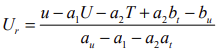
where:
-
Ur — Radon background in the "downward" U window
-
u — Count rate in the "upward" U window
-
U — Count rate in the "downward" U window
-
T — Count rate in the "downward" Th window
-
a1, a2, au, at, bu, and bt — Calibration constants (see sections above for details on skyshine coefficients and calibration factors)
Applying Radon Corrections to Radiometric Windows
The contributions to the other four windows, attributed to atmospheric radon, are estimated using linear regression. Background levels in the thorium, potassium, and total count windows are derived from the background measured in the uranium window, following appropriate calibration procedures.
The regression relationships used for radon background estimation are defined as follows:
-
The radon background in the upward-looking uranium window is related to the radon background in the downward-looking uranium window:

-
The radon background in the downward thorium, potassium and total count windows is related to the radon background in the downward-looking uranium window:



where:
-
ur — Radon component in the upward-looking uranium window
-
Ur, Kr, Tr, and TCr — Radon components in the respective downward-looking detector windows
-
The “a” and “b” coefficients — Required regression-derived calibration factors (see list above)
Radon Removal
The calculated radon background to remove is applied using the following formula (example shown for the output uranium channels):


where:
-
Uout — Output uranium channel with radon background removed
-
UpUout — Output upward uranium channel with radon background removed
Interim Channels
This method also generates interim channels in the database used for levelling: UTEMP, THTEMP, UPUTEMP, and UPURADREF. If deleted, these channels are automatically regenerated the next time the GX is run.
Removing Radon Background Using the Over-Water Method
Survey flights over water bodies—such as lakes or seas—produce no gamma‑ray response from the ground. Therefore, uncorrected radiometric data collected in these areas reflect only background contributions from aircraft, cosmic radiation, and atmospheric radon. If a large body of water is nearby, the survey may extend over the water intertwined with the survey over land. While over water, the survey must maintain a nominal constant altitude.
The tool leverages this principle through the over-water method.
This method should be applied after aircraft and cosmic corrections have been completed.
Creating the Over‑Water Mask
Your reference channel must be of class type "MASK". This True/False channel flags:
-
Over‑water records with a value of 1 (True)
You can mask a channel using the Mask Channel to Polygon option.
The system then automatically selects the corresponding records to calculate the radon contribution for each radioelement.
Filtering Requirements
Given the statistical nature of radiometric data, over-water data must be filtered over at least one minute.
Choose a filter width that:
-
Closely matches the average length of over‑water segments, and
-
Is short enough to prevent contamination from adjacent ground responses
Output Channels and Verification
The calculated radon backgrounds are interpolated across the survey and stored in the channels URADREF, KRADREF, THRADREF, and TCRADREF. Review these channels as profile plots to confirm that the values are reasonable and fall within expected ranges.
Radon Background Table Output
Radon contributions for potassium, uranium, thorium, and total count channels are written to the file _RpsWtBk_.tbl in the working directory.
The ASCII table contains six columns in the following order: flight, fiducial, uranium, potassium, thorium, and total count. Each selected data record produces one row.
-
For over‑water records, radon values are set to 0.
-
For over‑land records, interpolated radon contributions are populated in the appropriate columns.
Interpolation is performed across flights, not across individual lines. To ensure correct processing, line headers must include the flight number.
*GX.NET tools are embedded in the geogxnet.dll file located in the \Geosoft\Desktop Applications\bin folder. To run this GX interactively (outside the menu), navigate to the bin directory and specify the GX.NET tool in the required format. See the Run GX topic for more guidance.
References
- [1] G. Erdi-Krausz et al.(2003), Guidelines for Radioelement Mapping Using Gamma Ray Spectrometry Data, IAEA-TECDOC-1363, International Atomic Energy Agency.
https://www-pub.iaea.org/MTCD/Publications/PDF/te_1363_web.pdf - [2] IAEA (1991), Airborne Gamma Ray Spectrometer Surveying, Technical Reports Series - 323, International Atomic Energy Agency.
- [3] R.L. Grasty and B.R.S. Minty (1995), A Guide to the Technical Specifications for Airborne Gamma-Ray Surveys, Australian Geological Survey Organisation, 1995/60.
https://www.ga.gov.au/bigobj/GA7667.pdf
Got a question? Visit the Seequent forums or Seequent support
Copyright (c) 2026 Bentley Systems, Incorporated. All rights reserved.
Privacy | Terms of Use