Deposits and Erosions
This topic describes creating and editing deposits and erosions. The topic is divided into:
- Creating Deposits and Erosions
- Deposits/Erosions in the Project Tree
- Refining Deposits and Erosions
- Surfacing Options for Deposits and Erosions
For a general introduction to how deposits and erosions interact with other contact surfaces, see Deposit and Erosion Contact Surfaces in Contact Surfaces.
Creating Deposits and Erosions
Lithology data is often the most reliable data source to use when building geological surfaces, and it is best to derive contact surfaces from lithology data when it is available. If no lithology data is available, you can create deposits and erosions from other data in the project. You can also create offset surfaces from other surfaces in the project, which is useful for creating a series of surfaces. See Offset Surfaces for more information.
Deposits and Erosions From the Base Lithology
It is best to derive contact surfaces from lithology data, when it is available. There are two ways to create contact surfaces from lithology data:
- Using the base lithology column assigned when the model was created. This is the process described below.
- Using other lithology information available in the project. This is useful when you have created an additional lithology column as part of correcting and working with the drillhole data. For example, if when building a geological model it becomes apparent that changes need to be made to the drillhole data, you can import additional data or create a new column using the split lithology, group lithology or interval selection tools. See Deposits and Erosions From Other Lithology Contacts for more information.
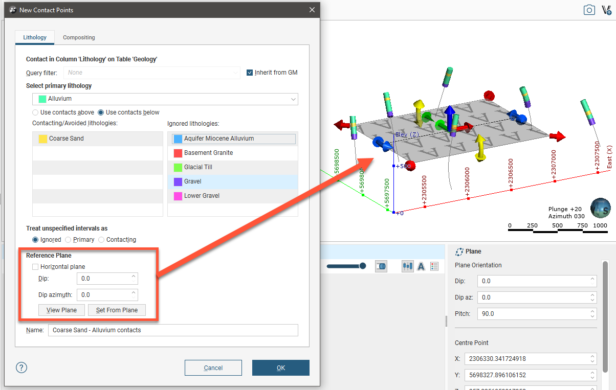
Selecting the From Base Lithology option opens the New Contact Points window:
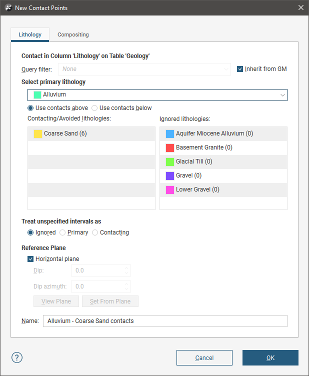
Select the lithology you wish to use to create the surface from the Select primary lithology list; this will be the older lithology (lower down) in the geological model. The Contacting/Avoided lithologies list shows the lithologies that contact the primary lithology and the number of contacts. This helps in selecting which contacts to use to create the contact surface.
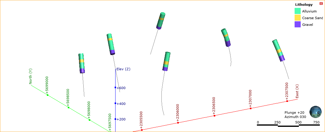
The options in the Lithology tab are useful for creating a surface when one lithology is interbedded with another. For example, here we can see that the coarse sand is interbedded with alluvium:
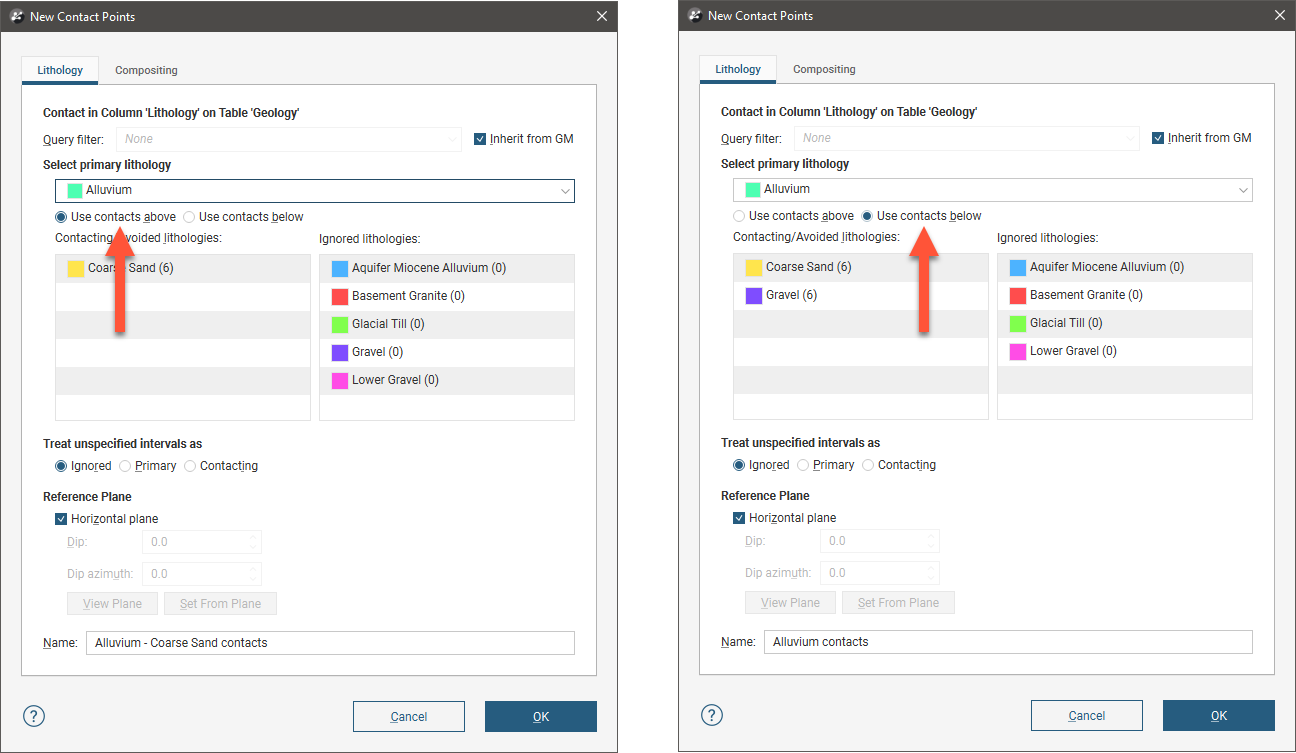
The solution to this is to create two surfaces from the Alluvium contacts, one using the contacts above (younger contacts) and the other using the contacts below (older contacts):
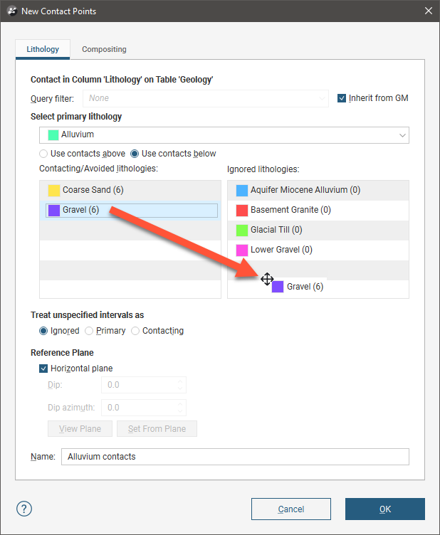
Note that the gravel contacts should be excluded for the surface created from the Use contacts below option, as we can see from the drillhole data that gravel appears lower down in the model than the surface we are creating. Do this by dragging the contacts that should be excluded to the Ignored lithologies list:
Unspecified intervals are intervals that have no data. By default, unspecified intervals are ignored when creating a contact surface, but you can also treat them as the primary lithology or as avoided lithologies.
For complex geologies, the up and down directions for the surface may not be clear. If this is the case, untick the Horizontal Plane box. A reference plane will appear in the scene, with the up-facing surface labelled A and the downward-facing surface labelled B:
When you disable the Horizontal plane option for the Reference Surface, the number of contacts is longer displayed in the lithologies lists, as the number of contact points is not updated when the reference surface used changes.
Controlling the position of the reference plane is similar to controlling the position of the moving plane:
- Use the handles in the scene window to move the plane.
- Set the Dip and Dip Azimuth values in the New Contact Points window. The reference plane will be updated in the scene.
Once the reference plane is correctly oriented, click the Set From Plane button.
Setting a reference plane for contact points is different from applying a global trend to a surface. To apply a global trend to a surface, double-click on the surface in the project tree and click on the Trend tab. See Global Trends.
Data can be composited at the drillhole level or on a surface-by-surface basis. To composite the data used to generate the contact surface, click on the Compositing tab. See Category Composites for more information.
Click OK to create the contact surface, which will appear in the project tree under the Surface Chronology. See Refining Deposits and Erosions below for more information on refining the contact surface.
Deposits and Erosions From Other Lithology Contacts
Creating deposit and erosion contact surfaces using the From Other Contacts option is useful when you have created an additional lithology column as part of correcting and working with the drillhole data. For example, if when building a geological model it becomes apparent that changes need to be made to the drillhole data, you can import additional data or create a new column using the split lithology, group lithology or interval selection tools. See Splitting Lithologies, Grouping Lithologies and Interval Selection for more information.
The process is similar to creating a surface from the base lithology column, but you must first select the lithology column you will use:
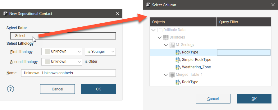
Select the First Lithology and Second Lithology, if known. Click OK. The New Contact Points window will appear. Assign the Primary lithology, Contacting/Avoided lithologies and the Ignored lithologies. These can only be selected from the model’s base lithology.
The rest of the process is similar to defining a contact surface from the base lithology. See Deposits and Erosions From the Base Lithology above for more information.
Be sure to add the contact surface to the scene to view it and check that it is oriented correctly.
See Refining Deposits and Erosions below for more information on the different techniques that can be used for adjusting a contact surface.
Deposits and Erosions From Other Data
If suitable lithology data is not available, deposits and erosions can be created from other data in the project, such as GIS data, structural data, points, polylines and surfaces. The steps for creating deposits and erosions from other data are similar, regardless of the data used to create the surface:
- Right-click on the Surface Chronology and select one of the data types from the New Deposit/Erosion menu.
- Select the data object that will be used to define the surface. This must already be in the project, unless you are using a polyline, in which case you are given the option to create a new polyline.
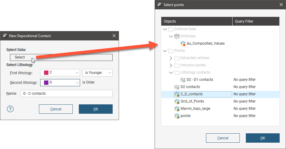
- Select the First lithology and Second lithology. These are the lithologies that will be assigned to each side of the contact surface. The lithologies you can choose from are those defined for the geological model in the Lithologies object (see Model Lithologies).
- Set whether the First lithology is older or younger than the Second lithology. Leapfrog Geo will, by default, put the younger side of a contact surface up, but this can be changed later.
Here, a points data object is being used to create a deposit:
For polylines, you first set the lithologies and the younging order, then click OK to move on to the next step:
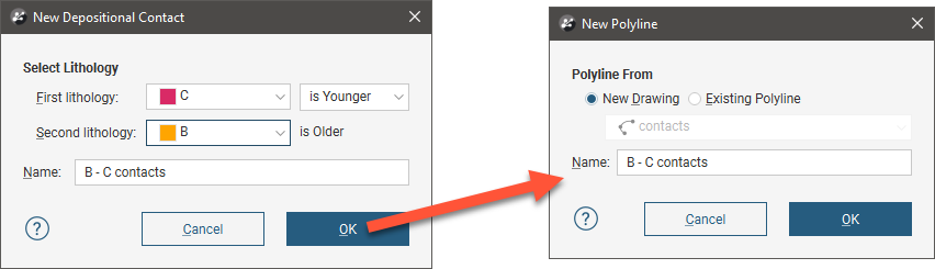
You can draw the polyline in the scene directly by selecting the New Drawing option. You can also use any polyline in the project by selecting the Existing Polyline option. You can then select the required polyline from the list.
The new contact surface will appear in the project tree under the Surface Chronology. Add the contact surface to the scene to view it and check that it is oriented correctly.
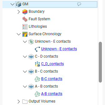
Expand the surface in the project tree to see how it was made. Here, a number of surfaces have been created using different types of data:
If creating a surface from a new polyline, the polyline will not be able to be used elsewhere in the project unless it has been shared. To share the polyline, expand the contact surface in the project tree, right-click on the polyline and select Share. The polyline will then be available elsewhere in the project.
As further refinements are made to the surface, that information will also be added to the contact surface in the project tree.
Deposits/Erosions in the Project Tree
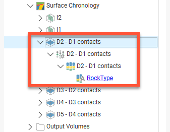
The name Leapfrog Geo automatically assigns to a deposit or an erosion is the lithologies assigned to each side of the surface. In the project tree, expand the surface to see how it was made:
Double-click on the surface to edit it. Double-click on the contact points object (![]() ) to edit the lithology and change compositing parameters.
) to edit the lithology and change compositing parameters.
As further refinements are made to the surface, that information will also be added to the project tree. See Refining Deposits and Erosions below for more information.
Refining Deposits and Erosions
You can refine deposits and erosions in several ways:
- Add other data. Right-click on the surface to see the options available, which will depend on how the surface was created. See Adding Data to Surfaces for more information.
- Edit the surface with a polyline. Right-click on the surface in the project tree and select either Edit > With Polyline. See Editing Surfaces With Polylines for more information.
- Edit the surface using structural data. Right-click on the surface and select Edit > With Structural Data. This option is available for deposits and erosions created from lithology data and other data in the project, but not for offset surfaces. See Editing Surfaces With Structural Data for more information.
To edit the surface’s settings, double-click on it in the project tree. In the Lithologies tab, change the lithologies assigned to each side of the surface, if required.
You can swap the younging direction if the direction was assigned incorrectly when the surface was created. The change will be reflected in the scene. Note that changing the younging direction does not change which lithology is older or younger.
The difference between deposit and erosion contact surfaces is how they cut older lithologies, as described in Contact Surfaces. For this reason, it is possible to change between the two types using the Contact Type setting.
For information on other techniques for refining deposits and erosions, see:
Surfacing Options for Deposits and Erosions
Surfacing options for deposits and erosions can be changed by double-clicking on the surface in the project tree and then clicking on the Surfacing tab. There are additional settings related to boundary filtering and snapping to data in the Inputs tab.
Boundary Filtering
When data objects are added to a surface, there are two ways to handle the data that lies outside the surface’s boundary:
- Filter the data. The surface is only influenced by the data that falls inside the surface’s boundary.
- Leave the data unfiltered. The surface is influenced by the data both inside and outside the surface’s boundary.
The Boundary filter setting determines how data used to define the surface is filtered:
- Off. Data is not filtered.
- All data. All data is filtered.
- Drilling only. Only drillhole data and data objects derived from drillhole data are filtered.
- Custom. Only the data objects specified in the Inputs tab are filtered.
Snapping to Data
Often, surfaces should honour drillhole data and treat data objects such as polylines and GIS data as interpretations. See Honouring Surface Contacts.
There is a Snap to data setting for a geological model as a whole that is set in the Geological Model > General tab (see Editing a Geological Model). Snap to data can also be set on a surface-by-surface basis by double-clicking on the surface in the project tree and then clicking on the Surfacing tab.
For individual contact surfaces, the options are:
- Inherit from GM. The setting for the geological model as a whole is used. This is the default setting.
- Off. Surfaces do not snap to the data used to create them.
- All data. Surfaces snap to all data within the Maximum snap distance, which includes drillhole data and any data added to the surfaces.
- Drilling only. Surfaces snap to drillhole data and data objects derived from drillhole data within the Maximum snap distance but not to other data used to modify the surfaces.
- Custom. Surfaces snap to the data objects indicated in the Inputs tab for each surface.
Take care in enabling snapping and in selecting what data the surface will snap to, as the more data you include, e.g. by setting a large Maximum snap distance or selecting All data for Snap to data, the greater the possibility that errors in the data or assumptions inherent in interpretations (e.g. polylines) will cause distortions in the meshes. If you do enable snapping, it is best to snap only to drilling data. See Honouring Surface Contacts for more information on these settings.
If you need a surface to honour drillhole data but treat other data objects as interpretations, select Drilling only. To honour some data objects while treating others as interpretations, select Custom, then click on the Inputs tab to enable snapping for individual objects.
Setting the Surface Resolution
See Surface Resolution for a Geological Model for information about the surface resolution settings in the Surfacing tab.
Applying a Trend to a Deposit/Erosion
There are two ways to change the trend for a deposit or an erosion:
- Right-click on the surface in the project tree and select Adjust Surface.
- Double-click on the surface in the project tree and then click on the Trend tab.
See Global Trends for more information.
Got a question? Visit the Seequent forums or Seequent support