
Height Correction
Use the RPS > Height Correction option (geogxnet.dll(Geosoft.GX.Radiometrics.HeightCorrection;Run)*) to correct for atmospheric attenuation caused by the sensor’s elevation above ground level. This tool adjusts airborne radiometric data to account for the air gap between the sensor platform and the terrain. Corrections are applied to the potassium (K), uranium (U), thorium (Th), and total count (TC) channels. For more information, refer to the Application Notes below.
To rerun the process with previous settings, select the header cell of any channel generated by this operation, then right-click to open the context menu. The last item in the menu is the most recently executed process (GX). Select it to reopen the associated dialog. From there, you can rerun the process using the existing settings, adjust parameters before execution, or simply close the dialog. Learn more about Dynamic Process Links (Makers).
Height Correction dialog options
|
Input channel suffix |
If Compton Stripping has been applied to the current database, the suffix used for the generated channels is automatically detected and preselected.
If multiple channel sets exist, all detected suffixes are listed, with the most recent one selected by default. Once you select a suffix, the associated channels are listed below this field. Script Parameter: SPECTRO.HEIGHT_CORRECTION_INPUT_SUFFIX |
|
Input total count (TC) channel |
Select the input TC channel. Defaults to Compton Stripping is not applied to this channel, as total count (TC) data is not spectrally separated. Script Parameter: SPECTRO.HEIGHT_CORRECTION_INPUT_TC |
|
STP altitude channel |
Select the STP-corrected altitude channel. Defaults to RALTSTP if this channel is present in the database. Script Parameter: SPECTRO.RALTSTP |
|
Nominal survey altitude (m) |
Enter the baseline altitude value to be used for height correction. To use the median height from the selected STP altitude channel, click the calculator button next to this field. Script Parameter: SPECTRO.NOMALT |
|
Height Attenuation Coefficients Specify the attenuation coefficients (per metre at STP) for your instrument configuration or survey characteristics. These values are retained after running the tool and are available the next time the dialog is opened. See the Application Notes for more details. |
|
|
Potassium (K) |
Enter the attenuation coefficient for the potassium (K) channel. Script Parameter: SPECTRO.KATTEN |
|
Uranium (eU) |
Enter the attenuation coefficient for the equivalent uranium (eU)*. Script Parameter: SPECTRO.UATTEN |
|
Thorium (eTh) |
Enter the attenuation coefficient for the equivalent thorium (eTh)*. Script Parameter: SPECTRO.THATTEN |
|
Total count (TC) |
Enter the attenuation coefficient for the total count (TC) channel. Script Parameter: SPECTRO.TCATTEN |
|
* Refer to the Radioactive Decay and Gamma Ray Emission section under Application Notes for more details.
|
|
|
Output channel suffix |
Enter the suffix to append to output channels. Default: As you type, the information string below the field updates to show the resulting channel names. Each name is formed by combining the radiometric element name with the suffix (letters and numbers only). Output channels follow the pattern element_suffix. Script Parameter: SPECTRO.HEIGHT_CORRECTION_OUTPUT_SUFFIX |
Application Notes
This tool operates on preprocessed channels generated by Compton Stripping, which are labeled *_strip when the default channel suffix has been retained. It then applies height correction and generates output channels labeled *_ht by default.
Radioactive Decay and Gamma Ray Emission
Potassium concentrations in rocks and soils are commonly estimated using gamma‑ray spectrometry, which detects the 1461 keV gamma rays emitted by the radioactive isotope potassium-40 (40K). Unlike 40K, which decays directly to a stable daughter isotope, uranium‑238 (238U) and thorium-232 (232Th) decay through long chains of intermediate, unstable daughter products.
For gamma-ray spectrometry, the energies associated with these decay series are identified through their most prominent daughter isotopes:
-
238U → 214Bi (bismuth)
-
232Th → 208Tl (thallium)
Characteristic gamma‑ray energy peaks — most notably the 1765 keV line from 214Bi and the 2615 keV line from 208Tl — serve as markers for the uranium and thorium decay chains. The intensities of these emissions are then scaled to estimate concentrations of uranium and thorium, reported as equivalent uranium (eU) and equivalent thorium (eTh).
Removing the Effects of Attenuation
In airborne surveying, the detector’s altitude varies continuously as the aircraft follows its flight path. To ensure consistency, data must be corrected to a nominal survey height. Within the typical altitude range encountered in airborne surveys, window count rates exhibit an approximately exponential relationship with height.
The estimated count rate at the nominal survey height is given by the following equation (IAEA, 2003 [1]):
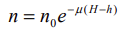
where:
-
n — Corrected count rate normalized to the nominal survey terrain clearance H
-
n0 — Count rate at STP-equivalent height, h
-
µ — Height attenuation coefficient for that window (per metre at STP) (*the linear attenuation coefficient in air is calculated during the calibration stage)
-
H — Nominal height or terrain clearance
-
h — Survey STP height (i.e., the height corrected for temperature and pressure)
Since air density—and therefore attenuation—varies with temperature and pressure, the height used in the equation above must be corrected for the ambient temperature and pressure.
Attenuation Coefficients
Before running the GX, you must provide attenuation coefficients for each channel. These values are typically supplied by your survey contractor, who conducts a trial survey at multiple altitudes over a defined calibration range. The procedure for determining these coefficients is outlined in the IAEA technical report [1].
Height attenuation coefficients for each window are calculated from data collected during the calibration survey, which is flown at various altitudes (e.g., 60, 90, 120, …, 240 m). The coefficients are derived from an exponential regression of each background-corrected and stripped channel count rate against detector height.
The illustration below is taken from the referenced IAEA [1].
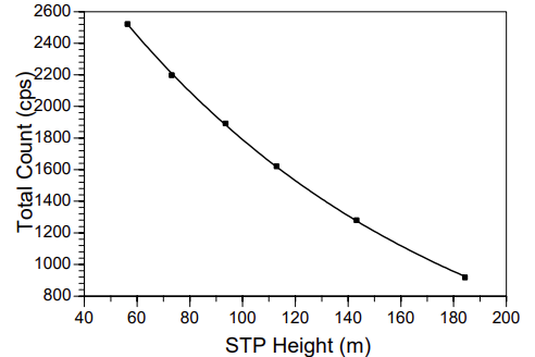
Height attenuation regression plot for the total-count window
Use coefficients (per metre at STP) appropriate for your instrument configuration or survey characteristics. These coefficients help correct for gamma‑ray signal loss due to air absorption, resulting in more accurate ground-level concentration estimates.
*GX.NET tools are embedded in the geogxnet.dll file located in the \Geosoft\Desktop Applications\bin folder. To run this GX interactively (outside the menu), navigate to the bin directory and specify the GX.NET tool in the required format. See the Run GX topic for more guidance.
References
- [1] G. Erdi-Krausz et al. (2003), Guidelines for Radioelement Mapping Using Gamma Ray Spectrometry Data, IAEA-TECDOC-1363, International Atomic Energy Agency.
https://www-pub.iaea.org/MTCD/Publications/PDF/te_1363_web.pdf
Got a question? Visit the Seequent forums or Seequent support
Copyright (c) 2026 Bentley Systems, Incorporated. All rights reserved.
Privacy | Terms of Use